In this six-fold, but still compact series of the successful implementation of lead-free soldering in the board assembly process, we have come to the final step. After implementing the technology on the shop floor, we must constantly follow-up, monitor and analyze the data in order to keep the process under control. Now we discuss cost and energy effects, and will see that the process needs to be verified continuously.
Gerjan Diepstraten, Vitronics Soltec
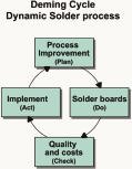
It has become clear that lead-free soldering will be introduced within a certain time frame. Many questions have been raised, although a lot of them have yet to be answered, such as the definition of lead-free, its implementation costs, and even if all technical issues have been solved. More and more experiments return good numbers on reliability of the new alloys. The process needs to be verified continuously since technology and expertise will be improved in an ongoing effort. We can use the Deming Cycle techniques to maintain control of the soldering process and make adjustments, improvements, and realize possible cost savings.
Material costs in wavesoldering
The solderpot of a given wavesoldering machine contains approx. 760kg tin-lead. Filling with tin-lead will cost about $3960. The density of SnPb is 8.4g/mm³. In order to fill this solderpot with SnCu (density 7.31g/mm³) we need:
Mass = 7.31/8.4 x 760 = 661 kg
This will result in an increase of 28% in solder cost to $5063. Other lead-free alternatives: SnAg (135%) and SnAgCu (145%) have even a higher impact on material costs.
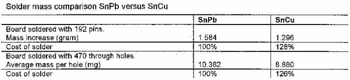
In regard to soldered joints and comparing tin-lead with the lead-free, we can suggest that the shapes are the same, and then due to the density, the mass of the lead-free alloys will be lower. For an SnCu through-hole pin connector the mass solder will be:
SnCu / SnPb x mass SnPb
Since we know that the joints look different, wetting might be poorer and angle of the joints are different. We need to verify if these calculated mass difference is more or less equal to real mass increase of the soldered joints. For the confirmation, we have soldered a board with connectors (192 pins/board) and weight the difference before and after soldering (the increase in mass is more or less the applied solder).
Flux issues in wavesoldering
As in all soldering processes, the correct flux plays a major role for the improvement of solderability and solder defects. In the event that we choose to implement a‘green’ process, we use VOC-free, water-based flux which has some advantages compared to alcohol-based formulations. Several experiments so far have proven that VOC-free flux shows better results with lead-free solder than no-clean flux. With respect to residues on the board and to solderability, they are preferred. One reason for this is the fact that the amount applied to the boards is minimized. The activators and chemicals in the flux react more aggressive in water than in alcohol. Although VOC-free flux is more expensive, the overall cost with this flux-type will be more or less the same (since the total amount used for soldering will be reduced) or even less.
If solderability improves, board rework will decrease. The reduced amount of flux also results in decreased equipment maintenance. Cleaning machine parts will be easier, and can be done with hot water rather than chemicals. Another cost issue with respect to flux is that, with VOC-free fluxes, no eco taxes need to be paid.
With regard to solder balls, we see an increase in the use of VOC-free flux. Part of this is due to higher temperatures in the process, which makes the solder resist softer. Compared to the tin-lead process, these solder balling is much easier to remove. In upcoming VOC-free fluxes the suppliers are attempting to dissolve rosin into the water-based formulations, resulting in a commendable decrease of solder balling. These investigations will continue, since most suppliers have not yet succeeded in finding the right formulation.
Impact on components
For many components, it will not be a major issue to change finishes. If there will be a big demand for lead-free finishes, it will be in the interest of manufacturers to switch over than it is currently. Since the techniques are already available, it is not expected that prices of these components will increase dramatically.
SnAg and SnAgCu balls for BGA packages appear to be an acceptable substitute for SnPb. Alternative lead finishes for packages are under investigation. Here, reliability and tin-whisker issues need to be addressed. The process temperature increase demands on component moisture sensitivity performance and package integrity. Plastics that can withstand higher temperatures (+280ºC for 5s) are being designed currently and will push prices higher. Therefore, it will be very interesting to have a reflow oven that has a high accuracy (small delta-T and good heat transfer) in order to be able to run lead-free profiles that meet the specifications of the less expensive components. If we can limit the max peak temperature to 245ºC, and still be able to bring all the solder above melting point according to the lead-free paste specification, this may result in a reduction of component costs for the user.
In this series, we have already discussed that in addition to banning lead, halogenated flame retardants from board materials will also be eliminated. This means that materials with lead-free finishes must be designed with preferable higher Tg values (glas transition point), to withstand higher process temperatures. These materials, as well as the lead-free finishes, will affect costs. How much these costs will increase is not clear at this stage, since the majority of board suppliers are still optimizing material selection and fabrication processes.
The use of nitrogen
The necessity of nitrogen in a reflow oven has been discussed often. Some processes require nitrogen, since it improves wettability and therefore results in better sol-der joint reliability. In other processes, nitrogen may result in more tombstonedcomponents and is therefore banned or controlled to a certain level. Even if an inert atmosphere in a reflow oven may help, the question still remains as to whether the costs are justified. Nitrogen is, in some countries, not that expensive (Germany for example $0.08/m3), whereas in others (Switzerland $0.81/m3), nitrogen is relatively very costly. It is preferable to have an oven that is capable of running in both air and nitrogen. For reasons of cost, an inert atmosphere should be avoided, but in the case of smaller and more complex designs, we always have then the ability to switch to nitrogen.
There is no general statement to be made regarding nitrogen. Every process has its own specific issues and challenges. After implementing lead-free soldering with higher process temperatures, we must review nitrogen performance and necessity. After a longer production period, we are able to evaluate if this decision was right.
As with tin-lead solder, in wavesoldering the lead-free solders oxidize quite rapidly when it is liquid at high temperature. Apart from inert soldering machines, the oxide film will be formed on the wave immediately after the oxide skin on the surface has been removed. Dross consists of solder enveloped by an oxide skin. With lead-free solders, the oxides on the wave may be more or at least clearly detectable visually. There are several reasons for this, apparently when we look at the lead-free process.
First, the tin content in lead-free solders is higher than in tin-lead. By far, the most common oxides on the surface of the solder are tin oxides such as SnO and SnO2. Second, the temperatures are higher than in tin-lead soldering. Higher temperature results in more oxidation, which results in more dross.
The amount of dross can be reduced. Some wavesoldering machines are fitted with a shaft sealing that eliminates dross formed at the pump shafts. Other dross is formed on the waves. By reducing the fall height of the wave (distance of the overflowing solder on the wave to the solder level), the amount of dross will be less. The use of nitrogen will also provide some benefit, because it is cost-effective, and the amount of dross can be decreased. Since oxides are only a small part of the dross, it is recommended to squeeze it. This will partly separate the solder metals from the oxide cells. In an experiment, we weighted the amount of dross formed in a tin-lead process and compared it with such of SnCu.
Energy consumption
Looking at the reflow process, we determine that we first need a lot of energy to heat up the board, then energy is needed to cool it down. Lead-free soldering requires different profiles and therefore shows different values of energy consumption. In the next experiment, we attempt to compare the power consumption of lead-free processes with traditional SnPb.
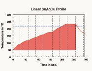
Using a datalogger, profiles can be developed of the time-temperature behavior of the assembly during the process. The area underneath the heating curve in a time-temperature graph is related to the energy needed to heat the assembly (figure 1).
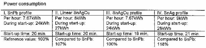
In the next experiment, we used a specific reflow oven and a typical board assembly to set up the profiles. In order to determine the power consumption, we installed a measuring device in the machine. The power consumption for every process was recorded, returning the following data:
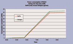
Figure 2 shows the power consumption of a reflow oven duringa shift. The SnPb (profile I) is compared to the linear lead-free profile (profile II from the table).
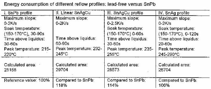
From the linear profile, we learn that a long time above liquidus not only results in increased intermetallic growth (which is not preferred for reliability reasons), but also has a big impact on power consumption. Profile IV has high peak temperature settings, which require a lot of power to keep the setpoint.
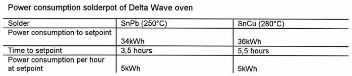
In the wavesoldering process, we have two areas where we can expect an increase in energy consumption due to higher melting points and process temperatures. The first is the pre-heating of the assembly. If we compare a no-clean flux application to a VOC-free water-based process, we can find an increase in energy consumption, due to higher preheat temperatures to a maximum of 25%. Second, since the solder temperature is higher, the solder-pot needs more power. Comparing an extreme high soldering temperature of 280°C with the regular 250°C (SnPb), we find the data shown in the lower table.
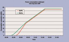
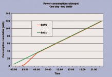
Figure 3 shows the power consumption of a specific solderpot during the day in a one-shift production, and figure 4 the consumption of a solderpot during the day for two shifts.
Operational costs
In general, lead-free wavesoldering requires longer contact times to achieve good wetting of the solder. This reduces the throughput. If necessary, the machine can be fitted with a different wave-former. If this is not enough to achieve proper wetting, conveyor speed must then be reduced. This may result in lower throughput.
The solder joints look different and exhibit different shapes. From what we have seen in lead-free implementations thus far, we have learned that the number of defects doesn’t increase. Nevertheless, there are other defects then such as fillet lifting. Reliability tests have not shown lower quality due to fillet lifting, so there is no need to repair these joints. For repair, we also see an increase of oxidation of the soldering iron tip.
There is no reason to expect an increase in maintenance due to lead-free soldering. VOC-free, water-based flux may even reduce maintenance time and intervals compared to no-clean. For reflow soldering, a good flux management system will reduce maintenance costs. New solder paste with different flux will evaporate other residues at higher temperatures, but it is not expected that this will result in a major increase in maintenance intervals or time.
New materials
After implementation, the process must be continuously controlled, improved, and redesigned in order to save costs and be competitive. Therefore, all those responsible for lead-free assembly should be aware that other materials, as well as process and machine upgrades will be introduced soon. Although some companies are already producing lead-free assemblies for some time, there are some issues in regard to alloy selection.
We see that it is very difficult to stay within the specification limits of the alloy, particularly with SnAg, in the event that there is copper present in the board material (copper pads with OSP coating). We see a trend that companies more and more select SnAgCu as the alternative for SnPb, and SnCu is used only in wavesoldering for cost reasons.
SnZn and SnZnBi are still outsiders for reflow soldering for the foreseeable future. If paste suppliers are able to design a superior flux system for these solders and succeed in eliminating the problems of oxidation with zinc-bearing alloys, these alloys might spark renewed interest due to their low melting point and costs.
Most of the companies that began with lead-free soldering already did not modify their board design for these new processes. If more and more knowledge about lead-free solder joints (reliability in relation to design dimensions) will become available, design rules may need some updating.
Since new developments will be introduced in different areas of the lead-free soldering process, this requires a continuous use of a standard improvement model, i.e., the Deming Cycle (figure 5) for the ongoing improvement of the assembly procedure. Follow this model to implement (or for the decision not to implement) developments such as the introduction of a new flux. The way to act is as follows:
Planning
Plan an experiment to find out if this flux will improve quality, reduce costs or another goal that has been selected
Do
Run the experiment
Check
Analyze the result of the experiment and judge if this flux meets expectations
Act
Implement the flux in the process and keep on monitoring the quality
With the Deming cycle, the end of this implementation program and of our series has been reached. Although lead-free soldering is a hot item, apart from the major companies, most manufacturers are still gathering information or have only just begun their first trials.
EPP 162
Zusammenfassung
Zwar hat die EU ihre Direktive zur endgültigen Einführung der bleifreien Elektronikmontage in einem Akt blinder Hörigkeit gegenüber kurzsichtigen Einflüsterungen von 2004 auf 2006 verschoben, doch kommt der Druck für einen schnellen Übergang klarerweise aus Südostasien. Europäische Provinz-Lobbyisten sind hier nicht gefragt. Will man in der europäischen Elektronikmontage nicht – ähnlich wie in der Halbleiterfertigung – auf hintere Plätze verwiesen werden, muß man jetzt handeln. Damit von den bisher eher akademischen Erörterungen des Themas eine direkte Übertragung zu den praktischen Fragen direkt in Fertigungslinien erfolgt, werden wir in einer Reihe von exklusiven Beiträgen hier für weitere Klarheit sorgen.
Résumé
L’UE a repoussé de 2004 à 2006 sa directive relative à l’introduction définitive du montage électronique sans plomb dans un acte de sujétion aveugle à des considérations à court terme, mais la pression pour un changement rapide vient clairement d’Asie du Sud-Est. Les lobbies provinciaux européens ne sont ici pas à leur place. Si l’on veut éviter que l’assemblage électronique européen soit relégué aux dernières places comme c’est le cas de la fabrication de semi-conducteurs, il est impératif d’agir maintenant. Afin que les débats plutôt académiques laissent la place aux questions concrètes et à des répercussions pratiques sur les chaînes de fabrication, une série d’articles exclusifs sera publiée en vue d’assurer plus de clarté en la matière.
Sommario
È vero che la CE ha rimandato dal 2004 al 2006 la sua direttiva per l’uso di impianti di montaggio di componenti elettronici senza uso di piombo, seguendo dubbiosi suggerimenti, ma è chiaro che la necessità di un passaggio il più rapido possibile ha le sue origini nel sud-est asiatico. Il lobbismo di alcune province europee arreca più danno che vantaggio. Se nel settore europeo dei montaggi di componenti elettronici, come già successo nella produzione di semiconduttori, non si desidera retrocedere rispetto alla concorrenza, è necessario agire ora. Per fare in modo di poter passare da discussioni accademiche all’applicazione pratica delle tematiche nelle linee di produzione provvederemo a chiarire tale argomento in una serie di esclusivi articoli.
A free guide on CD ROM
The basis of this series, published in the course of the year 2001, is available on CD ROM called the Five Steps to Lead-Free Soldering free of charge. For a copy just visit the home page of the company (www.vitronics-soltec.com) and simply click on the topic Free CD ROM. In addition to this guide, the technology group is also prepared to help; this contact is made via the web site, too.
Useful lead-free web addresses
Unsere Webinar-Empfehlung
.png)
Auch dieses Jahr präsentiert Koh Young wieder aktuelle Trends und „State of the Art“ Technologie aus der optischen Inspektion und 3D-Messung auf der Productronica in München. Aber wir alle kennen das Problem voller Terminkalender, Reisebeschränkungen oder fehlender Zeit, um in…
Teilen:


