

In Europe, under the WEEE (Waste from Electrical and Electronic Equipment) draft directive, the use of lead in solder will be banned by the beginning of the year 2004. We can expect that thermal profiling of reflow ovens will become more critical with this legal issue. Here a look of how profiles can be accomplished.
Phil Zarrow, ITM Consulting, Durham (NH) for KIC Thermal Profiling
Profiling is the process by which we determine the proper time-temperature durations a PCB assembly should sustain throughout the reflow cycle. These are dictated by such paste characteristics as alloy type, sphere size, metal content and the chemistry. The setpoints of the heat emitters and conveyor speed setting of the oven required to accomplish this for an assembly are affected by mass, surface geometry complexity, and substrate conductivity of that board as well as the oven’scapability to impart sufficient heat energy. The oven’s heat transfer efficiency and he operator’s experience affect just how much of a trial-and-error process profiling will be.
The EU WEEE draft directive is a tall order which would ban lead from electrical and electronic equipment as of January 1, 2004. This means coming up with a substitute for tin-lead, particularly Sn63/Pb37 and Sn62/Pb36/2Ag. Of primary concern in soldering is that the melting temperature be below 200°C and thus the reflow (full liquidus) temperature should be below 220°C, and even that is an uncomfortable thermal excursion for many components found on most PCB assemblies. The alloy has to be economical, and this puts a damper on indium and, possibly, large portions of bismuth. Regardless of which lead-free paste is used, the thermal-process window will tighten up significantly. As the proposed lead-free paste reflows at a higher temperature, the maximum peak will be limited by the most sensitive components (typically at 235 to 240°C), rather than by new pastes. The reflow profiling will therefore become one of the most critical process steps in the assembly line effecting product quality.
Reflow specification
When profiling a PCB assembly, each application will have a reflow specification. This specification is comprised of two temperatures which represent the minimum and maximum thermal excursions that should be present during the reflow soldering of that assembly.
The first temperature of concern is the full liquidus, also known as the minimum reflow temperature (T1). This is the temperature at which the liquidicity of the molten solder is ideal for flowing across the metal surfaces onto which it will wet (where adequately de-oxidized by the flux) and form the solder joint. It is determined primarily by the actual alloy of the paste but can be affected by the solder sphere size and other factors of the formulation, and may be stated as a range on the paste data-sheet. For example, for Sn63Pb37, the range averages from 200° to 225°C. The minimum value of the range given for the solder paste being used becomes the minimum temperature each interconnection being reflow soldered in that cycle must attain – no less. Again, this will typically be around 15 to 20K above the melting point.
The second component of the reflow specification is the most-vulnerable-component (MVC) temperature (T2). As the name implies, this application-specific value corresponds to the component on that assembly with the lowest threshold of thermal pain. Whatever that component is and temperature it gets into trouble at, subtract a buffer of 5K from that temperature and the resulting value becomes the MVC. This is the highest temperature any part of the assembly should reach. Staying below this will keep it out of trouble. The most vulnerable component may be a connector, a DIP switch, or it could be the substrate material or even the paste. It obviously varies from one application to the other and may require enlisting the assistance of engineering personnel.
Now that the range of temperature at the peak of the reflow cycle has been established, note also that the maximum tolerable gradient across the assembly is also determined (T2 – T1). Whether the board can stay within that band depends upon such factors as the mass and surface geometry complexity as well as the substrate composition of the assembly and the thermal transfer efficiency of the oven being used Ideally, a minimum gradient is desired with peak temperatures across the board as close to T1 (but no lower) as possible. This helps in reducing the liquidus dwell duration as well as the overall exposure of the assembly to high temperature excursions.
Rate of heating and cooling
Beyond this, reflow profiling is a matter of minimizing the liquidus dwell duration and matching the time-temperature intervals to what the solder paste manufacturer specifies. Regarding the rate of heating, most practitioners run at about 4K/s over a 20s-interval. This value is more or less application-specific and usually driven by component sensitivity to thermal coefficient of expansion differentials. Once again, component data sheets or manufacturers respectively should be consulted to assure safety. For a solder paste, running a heating rate in excess of 4K/s as measured over any 20s-interval could cause flux splatter and contribute to creation of blowholes and voids. The board laminate also prefers a rate of about 4K/s over a 20s-interval. Going faster risks vaporizing moisture entrapped in the laminate resulting in delamination.
Regarding cooldown, a good practice is to keep the rate of cooling the same as that of heating to avoid thermal shocking of components: the speed limit that applies going up should be the same going down. Hence a maximum of about 4K/s per any 20s-interval will be employed unless otherwise noted by the component manufacturer.
Preflow soak
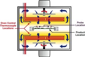
Prior to being ramped up to the melting point, the assembly is subjected to the preflow or soak zone. Traditionally this has been a thermal plateau typically between 150 and 170°C with a duration of from one to two minutes. Though the primary PCB assembly heating method is convection, there is a conduction element present as well. This is predominant in the board itself with heat being transferred from the hotter areas – those with the most surface areas such as the corners and the surfaces – to the cooler areas. The component distribution and mass as well as the actual thickness and composition of the board substrate will all affect this.
In earlier generations of reflow ovens, convection and infrared was the primary heat-transfer mechanism. These systems were not nearly as efficient in heat-transferefficiency as present convection-dominant (forced-convection) ovens. They therefore necessitated the incorporation of a soak zone to allow the colder parts of the assembly to catch up thermally with the warmer parts (as much as possible) prior to the final thermal excursion above the melting point to the reflow temperature. Faced with this reality, the paste manufacturers composed their flux formulations to be able to sustain this duration. How much and at what temperature varies among the flux formulations, a guide should be consulted regarding the preflow soak range and duration. Exceeding this soak duration can result in the flux prematurely drying out leading to dewetting and nonwetting. Note that there are a few formulations that do not want to see any soak dwell.
Tent profile
With the arrival of higher heat-transfer-efficient, convection-dominant (forced convection) ovens, for many assemblies a soak (preflow) may not be required. More and more practitioners have been resorting to a tent profile whereby the heating is constant through to reflow, and there is no soak dwell. Solder paste formulations in a guide that are denoted with a minimum soak time of zero are compatible with the tent profile, and a soak is not required. If desired, as for a more massive or otherwise complex board, a soak can usually be sustained (unless otherwise noted) but should not exceed the maximum time given.
Preheat
The first (approximately) 100°C of the profile is considered to be the preheat zone. Here, the fluxing activity on the interconnections is started and the solvents of the solder paste begin being driven out. There is some belief that in terms of thermal shock to components and board substrates, this is the most critical area for a rate of heating not to exceed 4K/s over any 20s-interval. Some component manufacturers recommend as little as 2K/s so it is important that the data sheets be consulted.
Once the reflow specification has been established along with the other profile parameters for the PCB assembly, thermocouples can be attached to the assembly and profiling commence.
Thermocouple attachment
Most important is the proper attachment of the thermocouple to the assembly. The thermocouple should not be affixed with Kapton tape because it does not consistently provide contact with the solder joint which is monitored. Likely, a highly inaccurate measurement combination of temperatures of air, tape and sometimes joint takes place. Attach the thermocouples with either a high-temperature solder alloy or a conductive epoxy. This may mean sacrificing an assembly to the „profile gods“, but with this a tool is present with which one can periodically check accuracy and repeatability of the profile for that board. In case of very low quantities and a high mix of boards, there are non-destructive, re-usable contacting probes available as well.
Use an assembly that is populated with the same component mix as it will be passing through the oven during the actual assembly process. Unless there is no reflow soldering of bare boards, profiling with an unpopulated board is fruitless. Thermocouples will be attached at interconnections (lead-to-pad junctions) that represent the warmest and coolest points on a board. The warmest item will typically be a low mass component (a small passive) located near a corner or edge of the board. The coolest spot will likely be an interconnect of a high-mass component (a QFP, PLCC, BGA, etc.) near the center of the board. Place other thermocouples at interconnections of heat-sensitive components (i.e. most vulnerable component) and other high-mass ones to assure they are seeing sufficient heat. Since a previously soldered assembly will be used, it is essential to remove the solder from the interconnects where the thermocouples will be attached. As the board was likely soldered with Sn63/ Pb37, perhaps Sn10/ Pb90 should be applied, if the thermocouple will be soldered with the latter, a „mystery“ alloy would wind up, one that will not sustain the multiple thermal excursions required of the test board. The original lower-temperature alloy will reflow and undermine the higher-temperature solder, and the user will lose the connection of the thermocouple. It is therefore mandatory that the existing solder at the interconnect be removed using solder-wick. This should also be done if there are conductive adhesive used attaching the thermocouple. Otherwise, the Sn63/Pb37 will reflow underneath the adhesive. As already stated, profiling is a tedious process and there is nothing worse than losing a thermocouple during a run as this means having to do it over again. Hence, this step is very important. After removing the old solder, apply a small amount of flux and then, using a soldering iron, use a small but sufficient amount of the high-temperature solder.
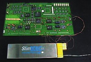
Use type K, 24 AWG or 30 AWG thermocouple wires, preferably pre-welded. After attachment, route the thermocouple leads towards the rear (in terms of direction of travel) of the PCB assembly. Some people prefer to terminate the thermocouple lead at the trailing edge of the PCB with a connector. The lead from the KIC traveller can then be quickly connected and disconnected at this point. Use any available holes in the board as well as Kapton tape to provide hold-down and strain relief to the thermocouple leads at appropriate locations on the PCB.
PROFILING PROCEDURE – STEP BY STEP• In the KIC guide, pull down the appropriate specifications for the solder paste formulation
• Establish the reflow specification for the PCB assembly – using the guide. Determine T1 (reflow or full-liquidus temperature), and T2 by finding the most vulnerable component (MVC)
• Attach thermocouples to the assembly
• Set heat emitters and conveyor speed of the oven to the recommended basic profile of the manufacturer
• With the KIC traveller attached to the thermocouple leads, run the board through the oven
• If using the KIC Prophet auto-prediction system (recommended) follow the instructions. If not, multiple runs may be required
• Assure that all test (thermocoupled) points have reached T1
• Assure that no test points have exceeded T2
• Assure that at no point in the profile, the specified rate of heating has been exceeded
• Increase oven conveyor speed to affect a reduction of liquidus dwell but assure that all points do not fall below the T1 value
• Upon achieving minimum liquidus dwell with all points above T1 (but below T2), assure that the preflow soak, if incorporated, falls within the temperature range and duration specified in the guide
• Assure that the rate of heating does not exceed the specified rate of heating at any point within the profile
Fax +1-619-673-0085
EPP 152
zusammenfassung
Das Reflow-Lötprofil einer Baugruppe (eine Zeit-Temperatur-Kurve) ist entscheidend für deren Qualität und Zuverlässigkeit – und somit für die Fertigungsausbeute. Für das Profiling stehen passende Werkzeuge zur Verfügung, deren Nutzung oft sehr komfortabel und zuverlässig ist. Mit den erwarteten höheren Löttemperaturen für bleifreies Lot wird Profiling bei „lead-free“ vermutlich ein praktisch unverzichtbarer Prozeßschritt.
Résumé
La courbe de soudage par reflux d’un module (une courbe temps-température) est décisive pour sa qualité et sa fiabilité, donc pour le rendement de la fabrication. Il existe, pour le profilage, des outils appropriés, dont l’utilisation est souvent très pratique et fiable. Avec les températures de soudure supérieures attendues pour la soudure sans plomb, le profilage deviendra probablement une étape pratiquement indispensable pour le „lead-free“.
Sommario
Il profilo di brasatura reflow di un gruppo costruttivo (una curva tempo-temperatura) è decisivo per la sua qualità e la sua affidabilità – e dunque anche per l’effettività della produzione. Per il Profiling sono disponibili idonei strumenti il cui uso spesso è molto comodo ed affidabile. Con le maggiori temperature di brasatura previsto per lo stagno senza piombo il Profiling per „Lead-free“ diventerà probabilmente una fase di processo a cui non si potrà praticamente rinunciare.
Unsere Webinar-Empfehlung
Applikationen aus dem Bereich der Leistungselektronik gewinnen immer mehr an Bedeutung. Die Inspektion dieser Applikation lässt sich mit der bewährten Standardtechnologie der 3D-Messtechnik bewerkstelligen.
Teilen:


