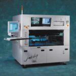
A flying prober is a type of in-circuit tester that does not require a bed-of-nails fixture. Think of a flying prober as the model of an in-circuit test technician, placing probes onto a circuit board assembly, switching the test modes as required, and recording the data against a known standard. Then increase the „tech-nician’s“ speed and accuracy and add more hands for more than two probes.
Edward Westbrook, flying prober product manager, Teradyne Inc., Walnut Creek, USA
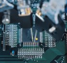
In most cases, a flying prober has four probes moving simultaneously over the topside of a board, and a number of stationary probes being held to the bottom side of the board. A Cartesian robot moves the probes. This robot uses stages for X, Y and Z motion to move and control the probes in three-dimensional space. As a probe touches a circuit test point, an instrument is switched to the probe automatically according to the program, similar to a bed-of-nails in-circuit tester. The flying prober quickly switches among different instruments and measurement value ranges (for analog test).
Flying prober advantages
Many people compare a flying prober to a bed-of-nails in-circuit tester (ICT). This is a useful comparison. However, it presents a limited picture because a flying prober may have additional functionality. A good example is that a flying prober can be equipped with a camera to provide a limited form of automated optical inspection. The most significant difference between a traditional ICT and a flying prober is that the prober does not need a fixture to perform ICT.
Lower cost of test – Fixtures can cost from $5,000 to $20,000. In a 10,000-unit product life (before any changes to the design to rev the board), this is a significant addition to the total cost of test per board (0.5 to 2 dollars each). Another way to think of the cost difference is this: for the equivalent of 25 fixtures (average cost per fixture $10,000 for an ICT), a flying prober system can be bought. Most contract manufacturers can create this many fixtures for a single line in less than a year.
Faster test generation times – Without a fixture to design and build, tests can be created much quicker. Typically, an ICT program and fixture is created in four to six weeks. A flying prober program is created and debugged in about two days. While we move towards the need for even faster product developments and introduction in order to take full advantage of market windows, design cycle time becomes a key factor in being competitive. Another, even more convincing payback analysis can be produced when it is known specifically how much sales revenue will be lost in this weeklong period it takes to develop ICT programs and fixtures (notto mention the strategic loss of market share), compared to the cost of a flying prober.
Easier design changes – There is a combined advantage of faster test generation times and no fixture cost. When final testing of a new product is being performed concurrent with production ramp-up, changes to the design are common. By not having a fixture to produce, both time and money are saved. In addition, test consistency is preserved because with a flying prober, the test can be modified quickly and easily. An entirely new ICT fixture can introduce errors that need another debug phase.
Another compelling advantage of the prober over a traditional in-circuit tester is that the prober can access more dense circuitry than an ICT.
Higher test coverage – For the most parts, ICT systems need a test pad of 1.016mm diameter. A flying prober can land onto a much smaller target. The most accurate probers can use a target of 0.2032mm diameter. This small target is not limited to test pads. Probes can contact component leads, connectors, and vias, for example. In modern circuit assemblies, it is becoming common not to have test pads because of shrinking available space and the loss of signal integrity when pads are designed into the circuit.
Flying prober disadvantages
Compared to the traditional in-circuit tester, a prober has lower throughput, more moving parts to maintain, and some test limitations.
Lower throughput – Compared to ICT, flying probers are slower because the probes must move to targets for each test. This mechanical action takes orders of magnitude of greater time than simply switching to another stationary nail in a fixture. When a flying prober „switches“ to another test, it retracts the probe from the previous target (moving up in Z), moves in XY to position the probe over the next target, and then places the probe (down in Z) to contact the target. Some flying probers take advantage of using magnetically placed stationary probes (not requiring any special fixtures) on a lift table below the circuit assembly. The table lifts spring-loaded probes to contact the bottom of the board. Increased throughput can be gained by placing these bottomside probes on test points that are used several times during the program, eliminating the need to make XY and Z moves to contact these often used points.
Mechanical maintenance – Flying probers are precise mechanical systems. The addition of a Cartesian robot introduces the possibility of lower mean time between failures (MTBF), because there are more systems at work than in an ICT that has fewer moving parts. These systems also have to be maintained. Before buying a flying prober, evaluate the three major types of Cartesian robots being used for flying probers-lead screw, linear motor, and surface linear motor.
Of these systems, surface linear motors are the simplest, have the fewest moving parts, and tend to be the most dependable. All of the Z heads of a surface linear motor operate on the same horizontal plane – typically four pucks floating on a flat surface. These pucks are the armatures of the motor. They ride on a very thin cushion of air over a surface that provides changes in magnetic polarity to move the heads.
Lead screw and linear motor mechanisms have a special problem to overcome when they have four Z heads. Two of the Z heads have to operate on a lower plane than the other two. If the probes are directed downward (this is the case for most flying probers), the Z heads on the top horizontal operating plane have a longer reach to the board under test. The probes typically are at an angle, so determining offsets between probes and alignment cameras becomes complex and relatively more prone to errors than with surface linear motors. In addition, the dynamic accuracy between the two pairs of probes is very different because each pair is operating under differing levers between the Z head and the end of the probe. The two probes further from the board are relatively less accurate than a system that has all of the probes closer to the circuit assembly.
Systems that use lead-screw-robots have a specific problem of developing backlash over time. Flying probers have to make several short moves for placing probes. This high amount of accelerating and decelerating moves are hard on the lead follower mechanism. Flying probers that use lead screws are suspect in the accuracy specification because this accuracy is short lived.
Test limitations – Another serious disadvantage of a flying prober is that the signal path is much longer compared to an ICT system. Longer signal paths are more susceptible to interference and signal degradation. These physics may limit the type of instrument that can be used reliably with a flying prober unless countermeasures are taken. Though most traditional ICT instrumentation can be used with a flying prober, be cautious when using systems for flash programming, boundary scan, and other high frequency digital measurements. Many flying probers use the very same suit of instruments as an ICT (typically a sister test product of the same vendor). These instruments may not be able to depend on the same signal reliability as the ICT. Moreover, the speed of that instrumentation is compromised. Companies that develop instruments specifically for their flying prober tend to have fewer but more fully developed instruments that provide the needed countermeasures to signal integrity problems. It is easy to asses these differing design philosophies by noting if the instruments are within the flying prober or cabled to an outboard card cage assembly that is also used by an ICT sister product.
Where to use a flying prober
Low-volume production and prototype runs – For low-volume production and prototype runs, a flying prober is by far the most cost-effective means of providing automated in-circuit test. As mentioned before, program development times and overheads are much less than with an ICT. In low volume, where overheads are spread over low numbers of boards, the savings by using a flying prober are much greater than the cost of slower test times per board. Simple financial models can represent the costs and trade-offs involved. However, the complexities of modeling the financial losses of being relatively late to market are subject to enough interpretation to make them hard to communicate. Nevertheless, it is safe to say that the benefits of being sooner to market distinguish market leaders from lesser companies.
High-volume production – This brings us to an area of growing interest for flying probers used for high-volume production. Though it is thought that a flying prober cannot keep up with the line rate of high-throughput manufacturing, using it in combination with other test equipment makes this possible. In high-volume, fully-ramped production, a flying prober can provide unique advantages.
With ICT to counteractloss of access
A flying prober can be very useful in countering loss of access on boards. The ICT performs the majority of the test, whilethe flying prober tests those areas the ICT cannot access. In this scenario, the accuracy of the flying prober becomes thekey factor in judging the usefulness of various systems offered. Simply put, the more accurate the flying prober, the more it can access. Current technology can probe a target as small as 0.2mm in diameter. It is important to review flying probers in terms of accuracy at the probe tip which has at least twice the error of the base robot. Due to problems such as a long length of probe mechanisms (long lever amplifying errors) and less accurate probe holders, many designs can have an order of magnitude with more error at the probe tip. Though many flying prober manufacturers specify the base mechanism accuracy, be sure to compare accuracy at the probe tip as well.
With AOI forsignificant savings
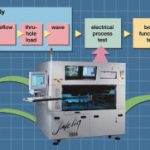
At the forefront of test and inspection strategy is the combination of flying prober and automated optical inspection (AOI). In this scenario, the AOI system looks for the majority of the faults: solder joints and part placement/presents errors. The flying prober performs minimal but necessary electrical test. Not only does this approach achieve excellent fault coverage, but cost savings as well.
No fixtures are required. In addition to fixture savings, the flying prober covers areas of high cost of failure that cannot be covered by AOI alone. A prime example is BGA packages. The AOI system cannot see the solder joints of the BGA, however in practice, the solder joint errors on a BGA are rare. Still, items such as loose parts below the BGA or a damaged BGA are common enough that a test of BGA integrity is important before presenting what can be an expensive board to functional test and possibly damaging it beyond repair. Tools available for flying probers such as boundary scan or DeltaScan (specifically designed for flying prober) can be useful in performing a quick check of BGA integrity. Another example of a high cost of failure is setting up the wrong reel and producing many bad boards. A flying prober can be used to sample the last part placed from each reel onto the board. This effectively limits the cost of this failure mode to one board.
In-line with functional test
A flying prober can also be used effectively as the sole ICT with functional test. This makes sense if there is a willingness to let non-catastrophic faults reach functional test. This also assumes the frequency of failure is low enough to make this strategy cost-effective. The flying prober can perform limited ICT to detect any faults that would damage the board beyond repair at functional test. This also is a fixtureless ICT strategy that yields the savings mentioned above.
During ramp up
In general, a flying prober can be used in any number of high-volume total test solutions as a ramping tool. While the high-volume tests are being perfected or fixtures are being produced, the flying prober can help produce parts for beta testing, market acceptance trials, or reliability testing, etc. The use of a flying prober has a direct effect on shortening time to market.
Combined with X-ray
The flying prober/X-ray combination is rare to date. This may be because it is an odd financial combination. Recently we have seen heavy promotion of the X-ray/ICT combination. An interesting observation is that the X-ray machine is expensive and slow (causing high overhead) but very complete in coverage of solder joint errors. The flying prober is more of a cost-effective tool. In general, those choosing to use X-ray as an every unit, 100% coverage tool for solder joints are not (and cannot be) as concerned with test overhead. For those companies, X-ray plus incurring the cost of fixtures for ICT is more common. It is also a general belief that inspecting BGA solder joints with X-ray is effective in finding faults. Counter to this belief is the fact that there is a very low incidence of solder errors on BGAs in a ramped process, and faults associated with BGAs are better found using electrical tests.
The future of flying probers
The use of flying probers in high-volume production will change the design philosophy for future systems. In the past, flying probers were designed and judged by how many features they had and how versatile they were in testing a variety of prototype assemblies. Now companies are starting to use flying probers in higher-volume production, where attributes such as speed, accuracy, and dependability are coming to the forefront of flying prober evaluations.
In the future, we should see more purpose-built flying probers that address specific needs. This is made possible by the fact that high-volume production usually justifies multiple systems being sold to the same end user for replication of test capabilities worldwide. With this, making more purpose-built flying probers becomes economically feasible.
EPP 183
Zusammenfassung
Immer wieder wird oft ziemlich engagiert diskutiert, ob und unter welchen Fertigungsbedingungen die Anwendung von Flying-Probern im Prüffeld sinnvoll ist. Klar ist: Dort, wo geringe Baugruppen-Stückzahlen relativ kostengünstig und rasch eine funktionelle und qualitative Evaluierung durchlaufen müssen, haben diese Tester gegenüber dem klassischen In-Circuit-Verfahren große Vorteile. Im Detail jedoch muß vor dem Einsatz stets die gesamte Fertigungs- und Prüfstrategie für ein Produkt gründlich analysiert werden.
Résumé
La question de savoir si l’utilisation de Flying-Prober dans un banc d’essai est judicieuse, et si oui dans quelles conditions de fabrication, donne fréquemment lieu à des discussions animées. Il est clair que ces testeurs présentent des avantages de taille par rapport à la méthode In-Circuit classique lorsqu’il s’agit de soumettre des quantités réduites de modules à une évaluation fonctionnelle et qualitative de manière relativement économique et rapide. Mais avant de recourir à cette méthode, il est nécessaire d’analyser soigneusement la totalité de la stratégie de fabrication et de contrôle pour un produit.
Sommario
Particolarmente accesa è la discussione se e sotto quali condizioni di produzione sia sensato usare Flying Prober nella fase di controllo. Una cosa è chiara: laddove delle quantità ridotte di gruppi costruttivi devono passare in maniera economica e rapida una fase di valutazione sia funzionale che qualitativa, tali tester hanno molti vantaggi nei confronti dei classici processi In-Circuit. Nel dettaglio, prima di essere utilizzati è necessario analizzare a fondo l’intera strategia di produzione di controllo per un determinato prodotto.
Unsere Webinar-Empfehlung
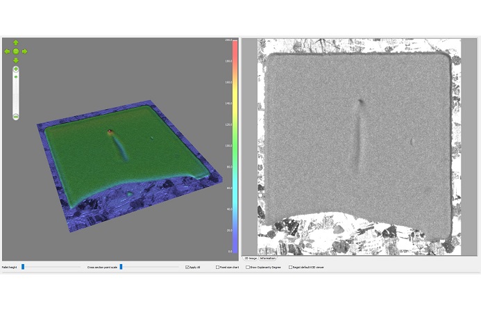
Applikationen aus dem Bereich der Leistungselektronik gewinnen immer mehr an Bedeutung. Die Inspektion dieser Applikation lässt sich mit der bewährten Standardtechnologie der 3D-Messtechnik bewerkstelligen.
Teilen:
