Part IV of this six fold article series on the transition to successful lead-free soldering deals with the design of a robust process. We continue with the knowledge gathered by the experiments and focus on making the process more stable, and consequently less sensitive to variation. This is necessary in moving from tin-lead procedures to an environmental friendly Pb-free process. Part I (introduction) was published in EPP Europe issue # 1/2, part II in # 3/4 (selection of material and equipment), and part III (Taguchi experiments) in issue 5/6.
Gerjan Diepstraten, Vitronics Soltec
The measure of robustness of a soldering process is its ability to maintain a stable output (yield) of board assemblies with a variable input. Input variations are caused by “noise” factors. A number of these factors will vary in surface mount technology (SMT) lines long before an assembly enters the reflow oven. All these variations require an optimum heating profile that must be minimally sensitive to all discrepancy, and a means to quantify the process capability:
•First, we will find that there is variation in the materials, including differences in solder paste properties (constituents, activators, lubricant, powder, oxides and printing characteristics), board materials (different suppliers, storage conditions), and component divergence.
•Second, there can be variation in the first part of the SMT process, such as solder paste printing and slump or component placement respectively.
•Third, there are ”noise” factors from the ambient conditions on the manufacturing floor, including temperature influence, as well as humidity.
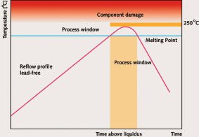
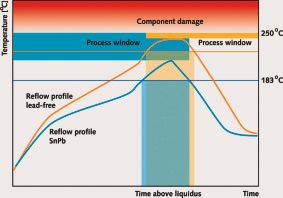
In reflow soldering, the use of lead-freealloys directly impacts process temperatures, and consequently the heating profile. Increasing the melting temperature narrows the process window, since the time above liquidus and the maximum allowed temperature of 250°C (to prevent component damage and board delamination) do not change.
Triangle profile (ramp-to-spike)
We can differentiate between different processes (those which are critical becauseof closeness to the limits of practicality in reflow soldering, and those that are less critical). For the procedures where the board is relatively easy to heat and the components and board materials have temperatures close to each other, onecan apply a triangle-sized (ramp-to-spike)profile. Triangle profiles are intended for products that have a small iT (the deviation in temperature across the completeassembly).
The triangle profile offers some advantages. For example, if the solder paste is properly formulated for a lead-free triangle profile, we will obtain shinier joints and improved solderability. It’s a prerequisite, however, that flux activation time and temperatures are compatible with the higher requirements of a lead-free profile. The ramp rate of a triangle profile is controlled over its entirety, and during the process it remains more or less the same. This results in lower stress in the PCB and component materials during soldering. The energy costs are also low-er, compared to a traditional ramp-soak-spike profile.
Ramp-soak-spike profile
Smaller components will ramp to temperature faster compared to larger parts; therefore, in order to be able to meet the requirements for time above liquidus for all parts, a ramp-soak-spike profile is preferred for these processes. The purpose of the soak zone is to reduce iT.
There are several sections in a ramp-soak-spike profile, resulting in too much stress in materials if not controlled properly. First, there is a preheating rate that is limited to 4K/s or less (depending on specifications). The flux constituents of the solder paste should be formulated due to the profile; too high a soak temperature can damage the paste performance (there should be enough activator left for the peak zone, where oxidation is most critical). A second temperature ramp rate (typical limit 3K/s) appears at the entrance to the peak zone. A third section of the profile, where particular attention should be paid to minimize stress, is the cooling zone. The maximum cooling rate for a ceramic chip capacitor, for example, is 2 to 4K/s. Therefore, a controlled cooling process is required, because this impacts the reliability of materials and the solder joint structure.
The best profile for a process canbe defined by a Taguchi experiment. Using noise factors in the experi-ment will help define which profile is more robust and least sensitive tovariations.
Evaluating the process
A Taguchi experiment produces the best settings for a process. In this step now, we begin with the settings, and run the first batch of products through the soldering machine. We want to quantify the stability of the soldering process over a longer period.
With statistical process control (SPC) we can stabilize a process and keep it under control, reduce variability and improve process capability. Typically, X-bar range charts and capability analysis are applied for this purpose. When the most influential parameters (defined with a Taguchi) of the soldering process are subjected to SPC, improvements with respect to stability and capability can be easily achieved. In a soldering machine, the hard and software has been designed to keep important parameters between specified limits around the setpoints. However, even when a parameter is within its deviation limits (and no alarm is generated), it can already be statistically out-of-control or showing a pattern that is unexpected due to historical data.
The keywords in the definition of successful SPC are ‘reduction of varia-bility’ with the distinction between ‘special cause variation’ and ‘common cause variation’. With control charts, we can eliminate ‘special cause variation’, the variation that can be linked to assignable causes. Capability charts are used for reducing ‘common cause variation’, a variation that is inherent and can only be reduced through process changes. In reflow soldering, typical parameters for SPC include the conveyor speed, the gas or heater temperature, time above liquidus, and the maximum peak temperature. In wavesoldering, typical parameters include conveyor speed, contact time, preheating temperature (PCB or heater), and the amount of flux applied to the board.
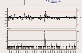
The X-bar range chart
An X-bar range chart is a graphical representation of statistical calculations on a variable, wherein the average and the range (i.e. maximum-minimum) per sub-group are employed to monitor changes in either the average or the range (this means the range is used as a measure of variation). Statistically significant changes may indicate process shifts, trends, cyclic patterns or out-of-control conditions. During the course of a day, sample readings were taken every 10s and divided into subgroups (5 samples per group). The averages and the ranges are shown in an X-bar range chart. The average temperature was 120.0ºC (setpoint 120ºC). The data originated from a thermocouple mounted in the preheat module. All machine data from the process, settings and measurement values were logged. The management information file can be imported into SPC software, which will return all manner of statistical graphs such as the X-bar range charts and capability analysis.
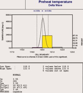
We have accepted preheat temperatures of 120 ± 2ºC, since we know that as long as the air temperature is within these limits, the board temperature will not fluctuate and will remain within the specification of the flux. The UCL (upper control limit) is 122ºC and the LCL (lower control limit) is 118ºC. We will get a Cp value which is an indicator of process capability.
Cp = (USL – LSL) / (6 x S)
Cp = process capability
S = standard deviation
Robustness and stability
Once we run the first batch of products with lead-free solder, we need to quantify the stability of the process. These factors can be measured on the product, like counting defects or data collected from the machine settings. For example, we can measure the temperature of a board with thermocouples mounted directly on the PCB, or measure the hot air temperature in the machine, which is related to the temperature on the PCB. Many operators have their own test board with thermocouples attached to it. Running the board in the reflow or wavesoldering machine will damage the test piece rather quickly. The board will begin delaminating and warping, and the thermocouples may become detached from the surface.
Another way of measuring stability is using special calibration tools that ride on the conveyor through the machine, carrying instrumentation. The advantage of using these tools is that this equipment is very robust, and a number of different parameters can be measured in one run.
Of the parameters affecting quality, the most are known from experience made with the SnPb process and from the results of a Taguchi experiment (part III) on lead-free. We begin counting and collecting the data of these parameters. After the SPC has proved that one parameter is under control (Cp > 1.66) for a longer period, the interval of measuring can be reduced. With SPC, it is important to focus on only a few, but most important parameters. Pareto charts will also help define those parameters to keep the process stable.
The X-bar range charts indicate process shifts, trends, cyclic patterns or out-of-control conditions due to special reasons. In some cases, preventive actions can be taken before out-of-control conditions actually occur.
Exhaust andtemperature conditions
With the introduction of lead-free alloys, temperatures will increase in all sections of an oven. For the cooling, a more efficient method than before is required, since peak temperatures are higher. Ovens meet these temperatures, but at this stage of implementation it’s a good idea to verify the machine temperatures.
The lead-free solder paste has a different chemistry than traditional SnPb recipes. Therefore, we have to deal with other residues, evaporating at higher temperatures. Thermal gravimetric analysis can help to define where and at what temperature materials evaporate. A sufficient flux management system is needed for a controlled removal of all residues. Additionally, the exhaust and its settings should be verified before implementation of the process in production.
Evaluating reliability
A number of reliability tests should be conducted for prediction of the product life cycle, and comparison of the data with standards of the SnPb process is necessary. Shear, pull and thermal cycle tests will tell more about the strength of a lead-free soldered joint. Cross-sections will reveal more about the thickness of the intermetallic layers and growth, which are related to reliability.
Release for implementation
With these tests conducted on a stand-alone, lab/demo or on a production machine during downtime, we have reached the next milestone in Pb-free implementation. Since all conditions have been satisfied, we can build on the following:
•The process is stable and repeatable
•Machine conditions are under control
•Solder joint quality, reliability is within the specifications
•Costs are still acceptable
Thus, the process can be released for implementation to transfer the technology down to the line. Before beginning with manufacturing, however, there is still much work to be done.
Project time schedule
Create a time schedule for all implementation activities. This schedule will incorporate not only purchasing materials, but also machine parts (if necessary). Then organize people and material provision to make adjustments, record procedures and OCAP (out-of-control-action plan), and prepare operators and engineers.
Quality issues
The material in the solderpot (wavesoldering) will be contaminated after a longer period of use. Try to establish specifications for the maximum allowed contamination of the alloy. Specifications or guidelines from institutes can help to define the maximum allowed amount of elements in the alloy. In some lead-free processes we see that already after 20,000 boards these limits are exceeded, resulting in the exchange of the solder, which of course is very costly.
OCAP procedure
In the event that the process is disturbed by ‘special cause variation’, this will show up in the X-bar- range charts. Most skilled operators will recognize this instability quickly. Rapid feedback is possible when the operator controls the stability of the process. A quick response is necessary in order to see the product affected as minimally as possible. To keep the pro-cess stable, the following steps are required:
•Regular verification of parameters
•Verify after every measurement if the process is still stable
•If the process is stable, continue without action. If not, the cause of disturbance should be determined according to the out-of-control-action plan
Operator training
Line operators should be prepared for the new process. The education should include instructions on machine options, different parameter settings (experience from Taguchi tests), changes in solder joint shape, dullness and other quality issues. Operators should also be trained in how to use SPC charts, and how to deal with the OCAP.
With the analysis and data from the Taguchi experiment, we are able to design a stable lead-free soldering process. The first batch of products is soldered with the procedures described in this part. Once the quality of the product is satisfactory and the procedure is found stable, the process is released for implementation. This is the beginning of many activities that have to be done before lead-free soldering is formally implemented, which will be described in the next part in the upcoming EPP Europe # 9/10.
EPP 159
References & acknowledgements
Statistical Process Control for Soldering, Frank J. de Klein, Vitronics Soltec, Oosterhout, NL
Cooling Parameters in Reflow Soldering, W. James Hall, Vitronics Soltec, Stratham,NH
Step-by-step SMT Process Control, Bob Kelley and John Weisgerber, SMT 2000
Reflow Profiling, The Benefits of Implementing a Ramp-to-Spike Profile, David Suraski, AIM
Robust Reflow Profile Design, Bob Rooks, 2000.
Zusammenfassung
Zwar hat die EU ihre Direktive zur endgültigen Einführung der bleifreien Elektronikmontage in einem Akt blinder Hörigkeit gegenüber kurzsichtigen Einflüsterungen von 2004 auf 2006 verschoben, doch kommt der Druck für einen schnellen Übergang klarerweise aus Südostasien. Europäische Provinz-Lobbyisten sind hier nicht gefragt. Will man in der europäischen Elektronikmontage nicht – ähnlich wie in der Halbleiterfertigung – auf hintere Plätze verwiesen werden, muß man jetzt handeln. Damit von den bisher eher akademischen Erörterungen des Themas eine direkte Übertragung zu den praktischen Fragen direkt in Fertigungslinien erfolgt, werden wir in einer Reihe von exklusiven Beiträgen hier für weitere Klarheit sorgen.
Résumé
L’UE a repoussé de 2004 à 2006 sa directive relative à l’introduction définitive du montage électronique sans plomb dans un acte de sujétion aveugle à des considérations à court terme, mais la pression pour un changement rapide vient clairement d’Asie du Sud-Est. Les lobbies provinciaux européens ne sont ici pas à leur place. Si l’on veut éviter que l’assemblage électronique européen soit relégué aux dernières places comme c’est le cas de la fabrication de semi-conducteurs, il est impératif d’agir maintenant. Afin que les débats plutôt académiques laissent la place aux questions concrètes et à des répercussions pratiques sur les chaînes de fabrication, une série d’articles exclusifs sera publiée en vue d’assurer plus de clarté en la matière.
Sommario
È vero che la CE ha rimandato dal 2004 al 2006 la sua direttiva per l’uso di impianti di montaggio di componenti elettronici senza uso di piombo, seguendo dubbiosi suggerimenti, ma è chiaro che la necessità di un passaggio il più rapido possibile ha le sue origini nel sud-est asiatico. Il lobbismo di alcune province europee arreca più danno che vantaggio. Se nel settore europeo dei montaggi di componenti elettronici, come già successo nella produzione di semiconduttori, non si desidera retrocedere rispetto alla concorrenza, è necessario agire ora. Per fare in modo di poter passare da discussioni accademiche all’applicazione pratica delle tematiche nelle linee di produzione provvederemo a chiarire tale argomento in una serie di esclusivi articoli.
Unsere Webinar-Empfehlung
.png)
Conformal Coating ist ein wichtiges Verfahren, um elektronische Baugruppen vor dem vorzeitigen Ausfall zu schützen. Damit bekommt der Beschichtungsprozess eine immer höhere Bedeutung. Dabei ist die Auftragsstärke ein wichtiges Qualitätskriterium. Nur eine zeitnahe schnelle Messung…
Teilen:


