A standard SMD placement machine cannot insert odd-shaped components due to its size, shape or weight. But in high-volume manufacturing it is economical to insert these through-hole parts (THDs), such as axial or radial taped devices, sockets, switches, transistors, etc., in PCBs automatically. This reduces rejects due to human error, lowers costs and helps to maintain high quality, but has a few pitfalls that can impact quality.
Kimmo Dammert, Director, JOT Automation
This is a common situation on the shop floor: in an automated manufacturing line, many components do not meet the requirements for processing with broad-spectrum placement machines. Manual insertion cannot be taken into consideration, as it would interrupt the production flow, besides of other problems. Apart from that, manual processing would not be cost-effective. The solution is to integrate an automated odd-form inserter in-line. With this concept, human errors are eliminated, but what about the difficulties that arise due to automation? So, lets have a look at JOT’s newly developed solution.
Selective soldering
When a board reaches the odd-shape insertion cell, the regular SMDs have already been soldered to the board. Now, the odd-shaped components are to be inserted in the board. Clinching is the first option to fix the parts to the board before being conveyed to a separate soldering process, direct soldering in the odd-shape cell is the second. This soldering process, however, is comprised of two challenges. The second soldering process may harm the SMDs – either because of the high soldering temperature or the humidity absorption stressing the SMD packages. The other issue is not to loose the already reflow soldered SMDs in a second soldering process. The solution to this difficulty is an immediate selective soldering process.
In certain applications, the odd-form insertion process can be combined with simultaneous soldering: the board arrives at the component-placing base of the cell via the infeed conveyor. The board is stopped, positioned and locked. The system inserts the component in the board, fed from the top. Positioning happens by inserting the locating pins into the corresponding holes of the board. Simultaneously, the soldering process takes place at the bottom side of the board. A gripper holds the part that is being soldered to the PCB, and clinching is not necessary. A solder bath and miniwave provide the soldering step. Flux is applied before with a drop-jet dispenser.
Both miniature wave and dispenser are mounted on a lower axis system. Therefore, programming to relate to the corresponding soldering positions is easy. The size and the form of the mini wave can be varied with various interchangeable nozzles. Hence, all sorts of different through-hole devices (THD) can be soldered to the board. A nitrogen inertion system on the wave and the solder bath ensures high solder joint quality. Such a work cell is especially useful when components need to be held for positioning during the soldering process. For this technology, JOT is partnering with a specialist soldering company in order to combine this expertise with automation solutions. This makes sure that the user gets the best of both worlds under one address. In some cases, for example when the wave cannot reach every part to be soldered, inductive soldering might be better than a selective method. With induction, a master con-troller monitors the soldering tempera-ture, the amount of solder and the heatenergy.
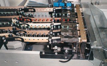
In applications without immediate soldering after insertion, a clinching unit ensures that the components are positioned and securely fixed to the board. The porting position of the parts onto the PCB could be supplied by an undemanding (passive) clinching plate mounted below the board standard fixing unit. However, for frequent production changeovers it is necessary to exchange the clinching plate, too. A more flexible but more cost-intensive solution is the use of an active clinching unit. Here, a 4-axis robot is integrated in the cell. The X, Y, P and W-axis are servo-driven by a robot and its controller, with P being the clinching pitch. The vertical stroke Z-axis is pneumatic and adjustable. The clinching tool is programmable in width for opening and closing; it is possible to clinch two pins in any direction.
Axis and gripper
Speed and precision are the crucial factors for an assembly line. Speed is influenced by the robotics‘ axis and gripper pick&place elements. For the insertion of different odd-shaped parts, various grippers are needed. An automatic gripper or finger change system is necessary to speed up changeover. For the automated insertion, the robot is equipped with an automatic tools exchange system. The tool holder is fixed on the Z-axis, and allows automatic change in accordance to the components to be inserted. The tools are stored in the gripper’s magazine station, and the robot can exchange them easily. The tool holder is also able to perform a special test to detect the appropriate insertion positions of the component leads.
The tools, customized to handle the different components, have a built-in sensor to detect the presence of the components in the gripper. In order to reduce the cycle time of the exchange, tools can be custom-built to handle different components. A detailed analysis helps to design special fingers able to manage different geometry using one gripper only. Generally, it should be possible to integrate these various gripper types: pneumatically driven parallel gripper with and without pusher, grippers for ICs and for axial and for radial components, vacuum gripper, a turret head with up to six different finger pairs or servo gripper.
A programmable servo gripper is very flexible and moves the fingers automatically. It can be used for plenty of similar parts. Handling times re reduced due to less gripper changes. As such a mechanism is not expensive, cost savings can be achieved. The gripper is equipped with a floating unit and a finger changing system. The floating unit is a pneumatical mechanism that controls the insertion of THDs. In case a THD is not inserted correctly, the part pushes against an air cushion, indicating the wrong position or a defective component to the system. The axis then will be realigned, controlled by a machine algorithm. For example, after three unsuccessful tries, the gripper eventually ejects the THD into a box and alarms the operator of the failure. With the finger changing system, it is possible to program the travel of fingers in relation to the component dimensions inserted by one type of finger pair. The servo gripper is fixed to the Z-axis of the robot. For exchange, it moves to the finger magazine, releases the pair of fingers and picks the next pair according to the program and insertion sequence. However, no matter which gripper type is used, the aim should always be to have as few gripper and finger changes as possible. Every change means a stop in the production flow.
In order to insert the components at their correct location, all axes such as X, Y, Z and W need to work precisely and reliably. To assure high quality and reliability, JOT has begun a partnership with Adept in order to integrate their Smart Modules into its placement cell. These modules consist of a family of precision ground ball-screw driven linear motion mechanisms. Their main features are: superior reliability and maintainability using AC brushless servo motors, a maintenance-free lubrication system, absolute encoders to avoid homing, and built-in power factor correction to eliminate power line conditioning. Moreover, the complexity of system wiring has been reduced since the amplifiers are mounted directly on the axis, thus eliminating cabling. 80% fewer cabling leaves more space for individual adoptions in the cell. Communication between the controller and amplifiers is provided through an IEEE1394 high-speed serial bus. Controller and amplifiers are highly integrated systems featuring very small volumes.
General requirements
Such an extra space can be used for feeders to be integrated into the odd-shape insertion cell. Depending on the parts, there are several possibilities for feeding the components from both sides of the cell: tube feeders (optional with lead cutting and calibration unit), radial feeders for tape-carrier presentation (with the option of pre-forming unit), axial feeders for tape-part presentation with or without stand-off and snap-in unit, loose feeders for axial components. Plugs and sockets or RF shieldings are fed out of trays that are stored in a tray feeder.
An effective way to shorten the board exchange time and boosting throughput is provided by segmented conveyors in the cell. The conveyor mechanism is divided into three independently working transport segments: infeed conveyor, pick&place conveyor and outfeed conveyor.
An insertion cell for odd-shaped components should of course meet many other requirements. With a user-friendly graphical interface that does not request complex commands, and sufficient networking capability, such an insertion cell straightforwardly integrates in varying environments. And, it is very useful when all machines on the shop floor have the same user interface. In conjunction with the machine controller, the host computer needs to perform the following jobs: control of the machine robot and control and monitoring of the board transport system. Furthermore, it handles malfunctions and displays error messages and includes a help system. Optionally, the computer can control the component loading and the use of the correct insertion program via barcode systems. In order to prevent unauthorized access and in turn maloperations, the administrator can set different user access authorizations.
Camera and vision system are necessary to ensure and control the bent leads of components, to check the orientation of parts and to inspect the fiducials for the orientation and alignment of a board. This system also supports the teaching of insertion positions on a board. Moreover, the use of CAD data helps teach the insertion process simultaneously on a PC. All-in-all, automated odd-form component insertion appears highly economical in high-throughput production environments. Fast robotics combined with efficient gripper technology increases the automation level by broadening the range of components processed. Providing that quality, reliability and precision are guaranteed; speed is always the most crucial factor in any automation measure.
EPP 193
Zusammenfassung
Für die automatische Bestückung von SMDs (oberflächenmontierbaren Baueilen) steht eine große Zahl leistungsfähiger Lösungen zur Verfügung. Hingegen ist die Insertion von bedrahteten Exoten-Bauteilen durchaus noch ein Feld für energisch vorangetriebene Entwicklungen. Bei solchen automatisierten Nachbestückungen gilt zur klären, ob man besser gleich lötet (ohne bereits plazierte SMDs zu beeinträchtigen) oder ob man die durchgesteckten Komponenten in den Löchern bis zum nachfolgenden Löten sicher fixiert.
Résumé
Il existe un grand nombre de solutions performantes pour le placement automatique de SMD (composants montés en surface). En revanche, l’insertion de composants exotiques câblés est un domaine susceptible de connaître des évolutions importantes. Pour ces rééquipements automatisés, il s’agit de clarifier s’il vaut mieux braser tout de suite (sans altérer les SMD déjà placés) ou s’il vaut mieux fixer de manière fiable les composants mis en place dans les trous jusqu’au brasage.
Sommario
Per il montaggio e piazzamento automatico di SMD (componenti montabili su superficie) si può oggi scegliere fra un grande numero di efficaci soluzioni. Al contrario, l’inserimento di componenti esotici cablati rappresenta ancora un campo dalle ampie possibilità di sviluppo. In simili post-equipaggiamenti automatizzati è necessario chiarire se sia più conveniente eseguire subito una saldatura a dolce (senza compromettere SMD già piazzati) oppure se si preferisce lasciare i componenti inseriti e fissarli sino alla successiva saldatura a dolce.
Unsere Webinar-Empfehlung
.png)
Auch dieses Jahr präsentiert Koh Young wieder aktuelle Trends und „State of the Art“ Technologie aus der optischen Inspektion und 3D-Messung auf der Productronica in München. Aber wir alle kennen das Problem voller Terminkalender, Reisebeschränkungen oder fehlender Zeit, um in…
Teilen:


