
Boards have evolved into complex and interacting systems. Test engineers often struggle to find out how these structures are initialized and booted because of poor documentation. Yesterday’s design-for-test (DFT) rules may actually be detrimental to successfully verifying those systems. One culprit is the boot-up process of the board and even individual ICs. What can be done to address this?
Kenneth P. Parker,Manufacturing Test Division, Agilent Technologies, Loveland Colorado, USA
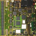
Boundary-scan (IEEE Std 1149.1) is a powerful test tool for complex board assemblies and systems, particularly as traditional in-circuit access through a bed-of-nails becomes increasingly difficult. Today it is not unusual to find a single board with over 500 components (50% digital) and 10,000 nodes with only 2000 (20%) or less actually accessible to in-circuit probing (example see figure 1). Such boards are extremely difficult to test without a limited-access method such as boundary-scan (BS). It adds not only controllability and observability, but also enables the automation of test development and pinpoint diagnostics. These benefits are completely lacking in the fallback practice of old functional testing.
For many years, engineers have been taught to observe certain rules that are absolutely necessary to create rock-solid, repeatable, reliable tests. These rules need to be re-examined now that boards, even individual ICs, may be considered complex systems in their own right. Indeed, a board may consist of many interacting systems. These interactions can introduce other testing problems that can be especially baffling for those who are unprepared.
Features of board systems
Twenty years ago, boards were composed of medium-scale integrated circuits and only worked as a system with other boards. This meant that a single board probably did not have enough logic on it to constitute a system. The board often did not have an oscillator either. Thus, the board did not ‘boot-up’, but more likelyresponded to a master reset signal. This signal was a natural target for test engineers, because they knew that asserting the reset would instantly bring the board into a well-defined state. But a few boards did have an oscillator, and this meant that after power was applied, the board was probably trying to ‘do something’. In these cases, engineers were quick to develop the rule that as well as asserting the master reset, they should also kill the clock by disabling it.
Disabling the clock had three salutary effects. First, it prevented the board (which was very likely only a portion of a system) from trying to do something that, due to the incompleteness of the system, was impossible. Second, it decreased the likelihood that the board might stumble into an inconsistent state (where, for example, a bus-fight might result), and third, it cut down on electrical noise that might complicate testing. Most systems of the past only had a single oscillator. Today, a board is a complex system or even a collection of interacting systems.
A board may contain hundreds of ICs, some with 105 to 106 gates, and contain multiple clock domains. Each domain could be a system in its own right, with asynchronous communication protocols between them. Even more interesting is that these ‘clocks’ may be hidden from the view of the test engineer because they are buried within an IC. The board designer may soon forget that these ‘crypto-clock’ domains are there because they are not a part of the mission function of the board, but part of the mission infrastructure. A perfect example of crypto-clock domain infrastructure is illustrated by a hypo-thetical field-programmable gate array (FPGA) paired with a complementary serial PROM (SPROM) as shown in figure 2.
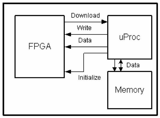
Upon receiving the initialization signal (the rising edge), an FPGA may request a download from a SPROM (the rising edge on download) which then communicates via a serial protocol with the FPGA, under the control of an on-chip clock buried in the SPROM (using the Write and Data signals). This download of mission functionality takes place in a few hundred milliseconds after the request, and then the FPGA takes on its mission function. Indeed, the Initialize signal may be tied to the positive voltage supply such that the applied power triggers the FPGA configuration as part of the process. Again, the board designer probably never counts this activity as a new clock domain. Worse, the test engineers, who cannot hope to be an expert in all ICs that will pass their eyes, may not be aware that the autonomous serial protocol even exists. (This is particularly true when some of the ICs contain programmable logic that is undocumented.) Figure 3 shows a second common scenario, where a microprocessor has the capability of programming an FPGA directly. This is an attractive design because it allows a circuit to be dynamically reconfigured under the control of software.
Some testingproblems of systems
What does this particular problem have to do with boundary-scan testing? Perhaps not too much if the serial download never interferes with the operation of boundary-scan. Sadly, it may well have serious consequences when it does. There are at least two scenarios known where trouble results. In one of them, boundary-scan in the FPGA simply doesn’t work while the serial download is operating. In another, the FGPA is incapable of communicating with its neighbors before or during the download because the device has pin parameters (like VIH and VOL) that are determined by the download. Thus, if the board does not successfully program such devices by itself, then boundary-scan will not operate correctly until they are programmed. The board test engineer may not be (at first) aware of this requirement, and it may be a difficult condition to satisfy if proper consideration is not taken.
For such a board, we must view it as a system test issue. We must be particularly wary of that critical time from the point of power application to when the board becomes ‘operational’. This is where many test problems are born. We simplify this problem here by assuming only one power supply where several may exist, that could be turned on in sequence.
An example from practice
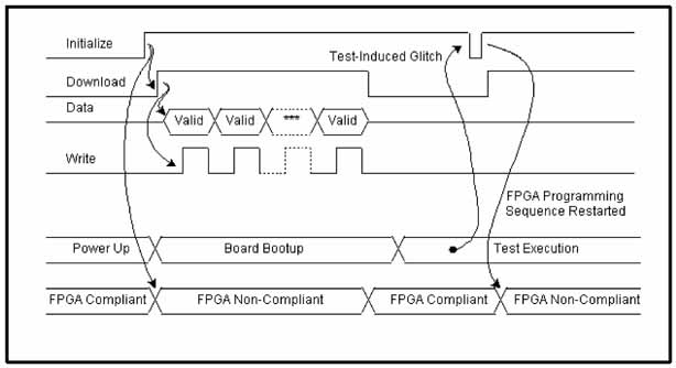
A board being tested was a collection of four obvious systems, each containing a microprocessor. Each microprocessor had a nearby FPGA it could dynamically load with a code. Moreover, a dozen additional FPGAs loaded their programming from nearby SPROMs. An example of the problem with autonomous FPGA programming is illustrated in figure 4.
This board powers up and then downloads code into its FPGAs. Some of these FPGAs are triggered by power-up directly, by sensing a rising edge on the power supply rails. Others are triggered by signals ultimately derived from the microprocessors. When testingbegins, ‘foreign’ signal activities occur which can trigger a programming initiation pulse on an FPGA. This causes the FPGA to begin its autonomous programming sequence, except now the test prevents it from completing, since the system has been ‘lobotomized’ by boundary-scan, that is, it no longer can respond as the designer intended for program downloading. Unfortunately, these FPGAs are not compliant during the download process. In this real case, certain FPGAs became non-compliant during boundary-scan testing, ruining the integrity of the BS infrastructure and leading to nonsensical failure diagnostics. The only way to recover the proper operation of the board was to cycle the power. This board was especially troublesome since at the time of test initiation, it was not clear if all the FPGAs were in a compliant state. It is also difficult to determine if the test itself would cause any FPGAs to suddenly begin a programming sequence.
A board designer may be forgiven for not having a ‘failing’ mindset. The job is hard enough just trying to fathom the correct operation of the design without considering the way it might not work. Thus, the natural inclination of designers is to overlook the issue of what might happen during the power-up sequence that could frustrate its success. However, the test engineer must consider how a board powers up, and what could go wrong with that process. In the next sections, we will discuss old and new ways of looking at this problem.
Some previous DFT rules
In the past, test engineers wanted to control a board from the very beginning, as soon as power was applied. So, two rules have resulted: assert any reset you can find; and, second, kill any oscillators you can find, preferably with the ability to insert a tester-controlled clock signal at will. This tester-controlled clock usually had a much lower frequency, and would only be injected during the testing of certain devices that needed it. The two rules guaranteed that a board would be, at power-up, quiescent and very likely in a consistent state (i.e., with no drivers in conflicting states). From there, it could (usually) be safely and repeatably in-circuit tested.
In boards common today, there may not be an easily identified reset, and there may be several clock domains. Further, one may not find all the clock domains simply by looking at the bill-of-materials for oscillator devices because of crypto-clock domains created by buried oscillators. Finally, since many boards now contain configurable logic devices, the configuration of the board may not be established until significant time has passed after power-up, provided nothing interferes with the configuration process.
New DFT considerations
Test engineers are now faced with other considerations. Should master resets be asserted during power-up? Should master oscillators be shut down? The answer seems to be ‘maybe’. It is very helpful to have the board designer available to discuss these questions, but that is often an unobtainable luxury. Thus, we need other DFT rules which can be used to frame this discussion early in the design.
There seems to be two approaches to powering-up for test. One, the old approach, is to disable all clocks and assert all resets continuously as power-up occurs. We call this an unbooted board. The newer approach is to allow the board to boot itself up after power application by waiting for some interval of time beyond power stabilization for the intelligent actors (microprocessors executing PROM boot code, FPGAs conducting autonomous downloads, etc.) to complete their boot processes. This is called a booted board. If testing a board depends on it being successfully booted before a method such as boundary-scan will work, then we have new considerations. Here are some questions regarding the testability of a board:
• Does the unbooted board have a working configuration, or does it, depend on the boot process to establish, have the ability for ICs to logically communicate?
• How sensitive is a booted board’s boot process to disruption? For example, would a commonly expected failure prevent from booting-up successfully? This is akin to judging the fraction of possible failures that can prevent boot-up and asking if the risk is acceptable.
• If boot-up is critical to success, how can we tell if we have achieved it? This may prevent many “untestable” boards ending up in a bone pile.
• If boot-up is critical to success, which nodes should not be probed with in-circuit nails because of loading effects that can prevent the boot process from operating correctly? For example, nails on system clocks should be avoided to ensure the quality of these critical signals. Here we mean a full boot up, or enough boot-up to assure that testing procedures are successfully enabled.
• Are there processes on the board that, once triggered, prevent testing activities from working? The autonomous FPGA download is an example of this problem.
• If such a process can be triggered, how can we avoid it? If triggered, will it complete? How can we tell if it completed? If it won’t complete, what mechanism may be used to reset it? (Some FPGAs refuse to perform boundary-scan while being programmed, and this process may never complete if the expected serial process is disrupted. Indeed, the only way to recover may be to cycle power on the FPGA.)
Discussing these questions can quickly lead to design and test practices (rules) that can avoid many problems. These problems will usually lead to poor yield at board test and bad boards that are very difficult to diagnose, so there is a big payoff in heading them off.
Modern boards, now collections of systems, some of which are easily spotted, and others which are hidden (called crypto-clock domains) present novel problems for test engineers and the design teams. It is especially useful to form a test strategy early in the design that decides whether a board must be unbooted or booted before testing activities begin.
EPP 192
Zusammenfassung
Eines der größten Probleme in der Baugruppenprüfung ist, die Boards nach dem Anlegen der Netzspannung für den Test in einen bekannten Zustand zu bringen. Früher mal hieß es, für die Initialisierung den Oszillator kurzschließen und mit einem Reset den Bootvorgang zu erzeugen. Inzwischen sind auf komplexen Baugruppen mehrere Sub-Systeme ineinander verschachtelt, so daß die einfache Rezeptur von damals nicht mehr wirkt. Also sind wirksame, weitergende Strategien nötig, die von Schaltungs- und Testprogrammentwickler gemeinsam gefunden werden müssen.
Résumé
L’un des plus gros problèmes dans la fabrication d’ensembles est de mettre les cartes dans un état connu après l’application de la tension secteur pour le test. Dans le temps, on disait qu’il fallait court-circuiter l’oscillateur pour l’initialisation et provoquer le boot par un reset. Aujourd’hui, les ensembles complexes regroupent plusieurs sous-systèmes imbriqués, si bien que cette ancienne solution simple ne fonctionne plus. Des stratégies efficaces, plus sophistiquées, que les développeurs de circuits et de programmes de test doivent trouver ensemble, sont donc nécessaires.
Sommario
Uno dei più grandi problemi durante il controllo di gruppi costruttivi è quello di portare le schede in uno stato ben conosciuto dopo l’applicazione della tensione di rete per il test. Una volta tale operazione consisteva nella cortocircuitazione dell’oscillatore per l’inizializzazione generando poi la ripartenza (reboot) con un reset. Oggi però su complessi gruppi costruttivi sono montati in modo inscatolato numerosi sottosistemi, cosicché il vecchio procedimento non può più essere applicato. I progettisti di programmi di controllo e di circuitazione devono dunque collaborare al fine di trovare strategie più estese ed efficaci.
Literature references
IEEE Standard Test Access Port and Boundary-Scan Architecture, IEEE Standard 1149.1a-1993
K. P. Parker: The Boundary-Scan Handbook, 2nd Edition, Analog and Digital. Kluwer Academic Publishers, Norwell MA, 1998
T. W. Williams and K. P. Parker: Design for Testability – A Survey. Proceedings of the IEEE, Vol. 71, No. 1, Jan 1983
This article is based on a paper originally presented at the 2000 IEEE International Test Conference, October 2000. Printed with kindly permission.
Unsere Webinar-Empfehlung
.png)
Die 3D-Messung und Inspektion des Lotpastendrucks ist ein wichtiges Qualitätswerkzeug. Dieses funktioniert nur mit den richtigen Toleranzen und Eingriffsgrenzen.
Teilen:


