Die attach challenges continue to appear for equipment manufacturers as well as for users and circuit designers. Requirements calling for minimal transmission lengths, such as in microwave applications, demand highly repeatable and accurate placement. Eutecticattachment techniques are desired in high performance die attachapplications.
Zeger Bok, Palomar Technologies, Inc., Vista, CA
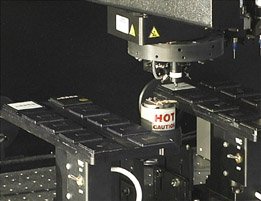
Eutectic die attach is not a new die bonding technique. It has been widely explored and employed, particularly on manual die bonders (see figure 1). But current and future needs – high volume and high placement accuracy (up to ±5µm) – call for flexible automated equipment. Automated workcells that present package materials via conveyors while providing the flexibility to support different carriers, and a range of attachment methods will continue to gain importance (figure 2).
The material characteristics will boost the ground plane performance as well as increase the thermal dissipation. Eutectic attachments can be a stacked geometry or multiple placements in one pass to the heated work area. The eutectic process, being very time sensitive, makes multiple layer processing a very challenging prospect.
Flexible automation
High volume and placement accuracy call for swift, precise and repeatable automation. Automatic workcells must provide the flexibility to support different carriers, such as wafers, waffle and gel packs, and a range of attachment methods, such as eutectic die attach, epoxy dispensing or stamping. The workcell must allow full automation by incor-porating SMEMA com-patible conveyors to present materials and transport completed parts. Changeovers and implementation of latest processes is the name of the game. These aspects should be encompassed by flexibility. Usually, placement accuracy requirements are situated around ±50µm, but demands narrow this requirement down to ±5-microns. Some companies have even reported manual mounting of active components down to ±1µm accuracy. Although this type of process has a very low capacity and requires a highly skilled operator, the manual method is usedbecause adequate automated equipmentis simply not readily available at thistime.
Design engineers typically develop products on manual die bonders, which will eventually be manufactured in an automated process. Although capable of far more, automatic work cells naturally perform best when parts are presented in an orderly fashion, and have consistent dimensions and appearance. It requires a certain effort to fit a manual to a bonding automated process, and design engineers should be concerned about automated process requirements early on in the development phase, to ensure work cell effectiveness.
Eutectic advantagesover other methods
Eutectic die attach offers a number of advantages over similar techniques, of which excellent thermal solder conductivity and immediate fixing after bonding are most significant. Eutectic solder provides excellent thermal conductivity characteristics, which makes this method suitable when a high degree of thermal dissipation is required, e.g. in radio frequency amplifier applications. Eutectic soldering tends to be a bit harder to establish than similar techniques, such as conventional silver-filled epoxy dispensing or stamping, but has a clear advantage in the attachment of power chips.
Dies are fixed immediately after the collet separates from the die, and no curing operation is necessary. With epoxy dispensing or stamping, accurate die placement isnot guaranteed until the parts are safe-ly transferred to an oven and cured.Eutectic attachment takes a bit longer, but is safe from die migration, and needs no curing.
Eutectic concepts
When different metals are combined into alloys, a range of melting temperatures is created with varying proportions of each metal. Material phases, such as liquid, solid, plastic, and also raster structure are usually depicted in phase diagrams. Amongst many things, phase diagrams show a distinct mass ratio at which solid evolves into liquid without passing the plastic state. This ratio determines the lowest possible melting temperature for an alloy, which is of great importance to the eutectic soldering process.
During eutectic die attach, the substrate is heated to a temperature just below the eutectic temperature of the solder. During bonding, an incremental thermal energy is supplied to the solder layer to promote the melting process. Liquified solder penetrates both bonding surfaces and an inter-metallic bond develops, called wetting. In many cases, an inert gas is employed during soldering, which usually contains a passive component (e.g. 90% nitrogen) to prevent metal oxides from forming, andan active component (e.g. 10% hydrogen) to break away oxides. The solder is usually precipitated to the die foundation or to the substrate surface, but can also be suppliedas a preform, i.e. solder pieces cut to a certain percentage of the die size. Preforms are a cheap solution to apply solder,but utilization requires an additional pick&place step. Also, preforms are not always as easy to handle and tend to vary in shape and size, which may complicate uniform solder distribution during reflow.
Critical parameters
Manufacturers usually specify process conditions, often gained from in-house experience, such as how much solder reflow is desirable to achieve sufficient mechanical bond strength, and to avoid voids between die and substrate. Every application has its own specific set of requirements, and some machine parameters are more critical than others, but all need to be in proper proportion to obtain the desired result. Critical control parameters include head force, background temperature and incremented thermal energy, soldering time, and inert-gas flow.
Immediately after placing a die on the substrate, the bond head pushes down on the die with a specified force. The amount of force must be sufficient to stimulate solder reflow, and to hold the die in place during reflow. Too much force can cause damage to a component, e.g. by introducing micro-cracks that may affect electrical performance. Small stress sensitive dies ranging up to 20-mil can take a fair amount of head force, typically up to 50 grams. Larger dies will generally require head forces of 100 grams or more.
The substrate is heated to a background temperature, which is boosted during bonding until reflowing occurs. The background temperature determines the amount of incremental thermal energy needed to initiate solder reflow. It indirectly controls soldering time. The time-span of head force and incremental thermal energy largely determines the extent of solder reflow, but also impacts the throughput time. Actual soldering time varies from a few to a dozen seconds, depending on die size. The flow of inert gas affects the rate at which the solder reflows, and determines the quality of the inter-metallic bond.
Accuracy andthroughput demands
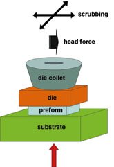
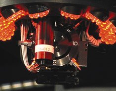
Several eutectic die attach methods can be used to successfully meet accuracy and throughput demands. Addition of thermal energy can easily be controlled if the bonder allows „scrubbing“, i.e. translating load force into frictional heat, by cyclically moving the die back and forth or left to right respectively, while exerting head force. In particular, if the number of scrubbing cycles and the displacement are programmable, this option offers great flexibility. Scrubbing requires eutectic die collets (see figure 3), which are typically composed of tungsten carbide and have either 2 or 4 slanted sides to support the die by the edges. Each eutectic die collet is tailor-made and fits the parts tightly to minimize drift during scrub. Nevertheless, a small amount of drift is usually noticeable in the scrub direction only. Therefore, the scrub direction will be chosen perpendicular to the direction with high accuracy demands, which proves to yield excellent results. Figure 1 represents eutectic die placement on a heated substrate, indicating substrate, die, preform, and die collet location. Notice the potential scrubbing directions.
If the workcell offers the flexibility to interact with third-party devices, a temperature controller with low mass, heat conductive strip (allowing fast heating and cooling), can be used to provide the additional heat for solder reflow. These devices usually control heat by mastering current flow through the strip, which acts as an electrical resistance. The workcell triggers the heat controller, e.g. as the bond head exerts force on the die. The background temperature is set below reflow temperature, and temporarily ramped up and held at a certain level, e.g. 10K or higher above reflow temperature, depending on the cycle time. This method proves to work well with solder preforms, and does not require scrubbing, although it may be beneficial for the increase of throughput.
With accuracy demands becoming more pronounced, close attention to mechanical imperfections, inherently connected to axis motion, is required. Picking dies close to the place site, presenting them in an orderly fashion to minimize rotational head movement, and carefully tuned machine parameters are key.
Dies presentation in wafer form or dies orderly arranged in a waffle pack can seriously reduce the time needed for an automated vision system to accurately locate a component. Also, repeatable sawing may reduce pick&place offset, as the vision system recognizes patterns on the component rather than the bare edges. This can be important when components need to be carefully aligned to ensure proper functionality, such as laser diode die on a carrier. The gold precipitation on top of the laser diode, which serves the wire bonding process, is not always accurate enough to locate the diode optical center. Often, specific marks or alignment points are available for manual referencing, which however are not always as easy to recognize by a vision system.
At higher placement accuracy, effective inspection methods become more difficult to find with standard optical equipment. High focal depth and magnifications up to 500x are minimal requirements for inspection as well as measurement. The vision system proves to be valuable for automatically inspecting proper placement on completed parts, and storing placement accuracy data. But placement accuracy entails more than positional and angular offset. It also concerns horizontal flatness of the die on the substrate, because even slightly tilted die can cause positional offset when placed into the package.
Application example
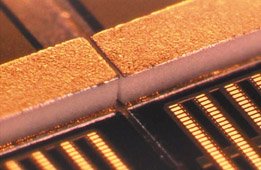
Figure 4 exhibits eutectic attachment of exceptionally slim die (20×200-mil) on a microwave application. Placement accuracy is rather forgiving (±1-mil) to allow constant wire bond length for tuning purposes, but the specific die shape makes even this requirement difficult to maintain. In this case, perfect horizontal flatness of the eutectic die collet is essential to avoid offset during placement. Scrub is used to provide the additional reflow heat and solder has been precipitated at the foundation of the die. The part was bonded on fixed temperature controlled heat stage. Specially designed eutectic die collets were necessary to ensure proper scrubbing.
Conclusion
To meet the volume and placement accuracies demanded by the telecommunications industry, flexible automated workcells are required that support different carriers, methods and automated materials presentation. The eutectic process, although time sensitive, provides advantages and proves to be capable of handling the technical requirements of packaging developments. They continue to evolve, however, requiring even higher placement accuracies. Significant technical challenges exist with respect to automated workcell capabilities.
Fax +1-760-931-5191
EPP 210
zusammenfassung
Halbeliter-Dies kann man auf unterschiedliche Weise auf dem Trägermaterial aufbringen. Der automatisierte Die-Attach auf Basis eutektischer Lotzinnformulierungen hat einige signifikante Vorteile. So ist die thermische Leitfähigkeit der metallischen Verbindung zwischen Substrat und Die höher als bei leitfähigen Klebverbindungen. Zudem sind gelötete Die-Bonds innerhalb weniger Sekunden fixiert, im Gegensatz zu Curing-Prozeduren bei Klebungen mit Epoxy.
Résumé
Les semi-conducteurs peuvent être appliqués de différentes manières sur le support. Le Die-Attach automatisé à base de formules eutectiques de soudure réunit certains avantages significatifs. Ainsi, la conductivité thermique de la jonction métallique entre le substrat et le Die est supérieure à celle des collages conducteurs. En outre, les Die-Bonds brasés sont fixés en quelques secondes, contrairement aux procédures de Curing avec des collages à l’époxy.
Sommario
I die in materiale semiconduttore possono essere applicati su materiale portante in maniera differente. Il die-attach automatizzato sulla base di formule di stagno per saldatura a dolce eutettiche possiede notevoli vantaggi. Per esempio la conducibilità termica del collegamento metallico fra sostrato e die è maggiore rispetto ai collegamenti a conducibilità elettrica eseguiti con colle. Inoltre die-bonds saldati a dolce vengono fissati entro pochi secondi, al contrario di procedure Curing nel caso di incollaggio con epossidici.
Unsere Webinar-Empfehlung
.png)
Auch dieses Jahr präsentiert Koh Young wieder aktuelle Trends und „State of the Art“ Technologie aus der optischen Inspektion und 3D-Messung auf der Productronica in München. Aber wir alle kennen das Problem voller Terminkalender, Reisebeschränkungen oder fehlender Zeit, um in…
Teilen:


