With the improvements in the software and hardware capabilities of flying prober systems, they have become a popular tool for manufacturing verification of board assemblies. What are the values of such a test platform, and when should it be considered as part of an overall quality assurance strategy?
John W. Ledden, GenRad, USA
In the past, board manufacturers focused on in-circuit and functional tests as the primary method to detect process and performance faults. In-circuit test required full nodal access, a bed-of-nails fixture, significant NRE cost, as well as the time needed to build and debug fixture and test program. Although there has been many improvements in this method, such as BIST (build-in self-test), boundary-scan and cluster testing has allowed for a higher fault coverage without full nodal access. Development and debug will likely increase, while diagnostic resolution will decrease. In-circuit test with full nodal access offers pin-level diagnostics, complete process verification and limited performance check with test time dictated by the desired beat rate of the manufacturing line. Functional test alone does not require any additional nodal access. However, it requires interfacing to the board connector(s) or external interfaces. This method ensures that the board will operate properly when integrated in a subsystem or final product. It is recommended that this be used as part of an overall strategybecause support for functional test ismore difficult. Diagnostics are often incomplete due to the high cost of creating extensive routines, and if not part of a distributed strategy there will be an increase in damaged products due to the appearance of process faults at this late stage of testing.
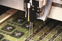
Flying probe testing has become more popular, because there are major improvements in the mechanical accuracy and measurement systems, dramatically improving the repeatability and diagnostic capability to allow users to verify the bill of materials (BOM) or the golden board approach. As part of an integrated solution, the program preparation imports CAD directly and generates a test program in a shorter period. This is a major advantage of second-generation probers, which result in quicker time-to-market. Finally, the ability to integrate third-party instruments has allowed probers to offer some performance testing as well as process verification. The rise in popularity is due to a number of reasons. Some of the drivers for this change are:
• Increase in low volume production
• Shorter product life cycle
• Time-to-market/time-to-volume issues
• Less traditional test point access
• Increase in PCB node count
• Contract manufacturer’s need for a quality check before shipment
Test access
There have been considerable improvements made in the quality of test provided by the second generation of flying probers. Test access should always be a consider-ation when deciding on a test strategy.The design for testability (DFT) rules will be dependent upon the method chosen. When using a contact test, it is ideal to have very large pads (40 mil) added to the PCB with multiple locations for powerand ground nets. This is not always pos-sible due to board density and performance issues. A flying prober in certain cases can make contact to smaller non-traditional access points increasing test coverage.
Throughput is often an issue with flying probing and unlike in-circuit test, probing locations should be selected (if there is more than one) as close together as possible. This will decrease the XY-movement of the probes and have a positive impact on test speed. This feature should be included in the test-point placement algorithm. Another issue is to minimize the height of the component on the probed board side. This will allow the programmer to minimize the Z-travel of the moving probes, therefore decreasing test time. If there are any connectors, daughter cards or shields, etc. above the maximum Z-height of the flying probes, they should be placed during an ‘operation after test’ to allow the UUT (unit under test) to be completely testable. Power and ground access would be best located on the opposite side. This will allow fixed probes to be placed on the most highly accessed nets for test and guarding, to raise test speed considerably and limit pad damage due to multiple probe strikes on the same location. This applies only if the prober supports bottom side contacting.
Since flying probes are often used when full physical access is not available or when DFT rules have not been observed, what access is necessary to get a repeatable test? If possible, test pads should be used, ideally at least 20 mil wide. If vias are used, the stacked tolerance of the drilling operation should be taken into consideration, and the area should be increased by this tolerance. If possible, all vias should be filled with solder to ensure consistent contact. Probe locations must have a separation of 16 mil center-to-center to prevent shorts. If the only location available is a populated pad, software is available on certain probers to automatically ‘offset’ the probe placement to avoid hitting the component lead itself. Hitting a lead should be avoided because placement tolerance could cause damage to the lead or result in a higher quantity of false calls. The program should be run repeatedly to ‘weed out’ the unreliable or non-repeatable tests, keeping in mind that repeated runs of the same board could be a cause of non-repeatable tests due to possible deterioration in the test point.
Fault detection
The first generation of flying probers used only the manufacturing defect analyzer approach of learn-and-compare as a way of testing. There were many reasons for this. Among these are quick time-to-market, no need for the bill-of-materials entry into the converted circuit description, and the inability of older-generation probers to get consistent measurements due to the fact that there are no fixed system residuals as with a bed-of-nails or edge-connector fixture. We have to note that unlike bed-of-nail systems, residuals in a flying prober are dependent on the XY location of the probes.
There have been a number of changes in the second-generation probers that have helped to improve the repeatability and accuracy of tests. A few are:
• Active probes to minimize measurement residual impact (buffering signals at the probe to reduce residuals)
• A guarding algorithm as part of test generation (places guards to allow forless debug and better repeatability andaccuracy)
• Test algorithm based upon component size and circuit configuration (multiple tests based upon more than the reference designator only)
• Probe residual ‘zeroing‘ technique on each ‘low value’ test (measuring the residual and subtracting that value for each critical ‘low value’ component)
• Improved instrumentation (more accurate and flexible supplies and measurement circuitry)
Second-generation flying probers have increased fault coverage dramatically by including UUT power-up, vectorless and limited digital tests. Power-up testing has allowed users to verify any on-board regulation, as well as ensuring that no damage will be done to the board during final integration by guaranteeing that the current draw of the assembly is within tolerance. Using a clamped supply will also assure the user that no damage will be done to the UUT or final product during integration due to undetected low-impedance shorts. Vectorless testing can insure that the device is placed correctly as well as being soldered. This class of fault was left untested with older flying probers. Important to remember is that in order to take advantage of this feature that programming must be automatic. When these tests are difficult to implement, they will not be used when the schedule does not grant extra time. The software should allow the programmer to provide the reference designator of the component, and the tool should do the rest. In the case of a capacitive technique, where a probe must be placed on the device, files received from CAD must contain the outline of the device and the distribution of pins, so a test can be written easily. Digital test on a flying prober is limited, but can be used to increase fault coverage if correctly implemented.
Two digital tests are of interest. The first important consideration for implementing is the number of driver/sensors and the fixturing to access them. Flying probers have a very limited number of movable probes, and digital test in a repeatable and dependable fashion requires fixturing. Though one of the reasons for using those systems is the lower NRE and the fast programming time, the cost of a fixture (time to build and debug) may outweigh the value in a low-volume or prototype environment. The number of driver/sensors in the prober must match to the device under test (DUT). With the size of devices growing it is not wise to invest in a system with enough resources to test large devices, and that cannot keep up with the beat rate of the line.
The second point is modeling of digital devices in a low-volume environment, since it is time-consuming to build tests for digital ICs. In an in-circuit test, the user must inhibit or disable the upstream components and on-board oscillators to achieve repeatability. This will require additional test resources and increased development time.
So, a good strategy for testing digital ICs is powering-up the board, then the verification of functional blocks from edge-to-edge. This will allow to ‘sample’ the output of a board to make sure it is alive before final test or system integration. Another strategy would be to use vectorless test for a device and vector testing for an area of a multi section device. This will check the power pins, which are usually left untested by vectorless, and insure that the correct device was installed.
There has also been integration done with instruments based on IEEE/GPIB, serial communication or PCI configurations. The driver for this has been the user that needs to do some small level of performance checks after process testing. The other value is to have all of the diagnostics recorded on one repair ticket. The instruments that have been used in flying probers range from a network interface card to a number of GPIB equipment. The downside to this integration is the increased program development time and the decrease in throughput due to added test(s). The use of boundary-scan tests and serial on-board device programming has been included by many flying probe customers using third-party solutions. Often they use vectors which can reduce program development time. These improvements have especially been important to low-volume manufacturers who require high fault coverage, process test, and limited performance test without the cost of a bed-of-nails.
Repair stage
One of the challenges was how to reduce the quantity of false failures? Reliable diagnostic information is important to ensure that repair will be completed quickly and correctly. False calls are also a WIP (work in process) issue, which create a retest backlog at the machine. This results in slower quality feedback into the line and higher tests costs. There have been many reasons for improved test quality, including mechanical accuracy improvements, improved links to CAD (make testing to a bill-of-materials more automatic), improved test algorithms, automatically added guards and improved debug tools, just to mention a few.
The goal of testing should not only be to assure that the manufacturer is shipping quality products, but also to monitorand improve the process and the parts suppliers’ quality. This first step in realizing this goal must be a repeatable and complete test program. This will insure that the diagnostics will be believable, the benefit of which will be shorter repair times and fewer repeated tests. With an integrated test solution, the processed CAD should be used for paperless repair. These repair systems have advantages such as board views, displaying the fail data received from the prober or other machines. Some solutions also have the ability to port and reference schematic files. These features can be important in decreasing the time-to-repair (TTR) and lowering work in process. This is because flying probers are mostly used for prototypes and low-production runs when the repair people are not familiar with the UUT. This causes wasted repair time, trying to find the failed component on the board and its schematic location. Some systems also have the ability to record repair information, and give (?) reference to that data under similar failure conditions providing troubleshooting advice. This is not necessarily a fit for many boards since a larger sample is desirable to gain troubleshooting data. However, if the low-volume board has a long production life, this strategy is sound.
Other important features
Other important features make a flying prober a more powerful production and quality tool. Fault coverage reports are extremely important as ‘proof statement’, providing the most value when they show the coverage by both the test method and for the total coverage achieved. This allows the user to determine what fault categories will be detected on each component and tune the test based upon the product or manufacturing-site fault spectrum. Mechanically, the machine should be quick and easy to calibrate as well as able to withstand a reasonable change in the facilities climate before recalibration is necessary. The robust equipment should match the requirements of the manufacturingenvironment. Utilization numbers haveincreased significantly because manu-facturing facilities are specializing inprototype, low-volume and quick-turn products.
If a flying prober is used for production or prototyping, test speed should be an important part of the evaluation criteria. However, we should note that test speed is a sum of factors. Prober-head movement speed is an important element; its optimization could have great impact on throughput. Optimization should be done before debug to ensure that test interaction due to the state of reactive devices does not cause additional work. Shorts and opens tests should be grouped at the beginning of the procedure to allow for the discontinuance of failures, reducing test time while providing the simplified diagnostics needed for fast and inexpensive repair.
Expectations of coming technology
The use of flying probers is increasing at a faster rate than the test industry. This is due to not only the growing market requirement for fixtureless test, but also to the many technological advancements. Although it is difficult to predict what feature sets will be added in the future, it is safe to say that flying probe technology will continue to evolve as its users ‘push the limits’ of capability. Certainly, there will be a drive for better and more automatic tools to assist in program development. Some of those improvements will focus on quicker, easier, and more complete development. With the responsibi-lities of test engineers increasing and the requirement for ‘quick turn’ programming, there is the need for more automated programming features including better links to CAD and achieving greater fault coverage with less engineering intervention.
We should also look for an increase in speed to reduce the cost of testing, to allow for easier justification of the investment and to better adapt as part of a distributive test in a high-speed manufacturing environment. The combination of X-ray and flying-probe with software to optimize coverage without redundancy will be of great value in prototyping. There will be the increased call for software to optimize the use of flying probers as part of distributive test with X-ray and functional in-line. This will allow manufacturers to reduce WIP by eliminating redundant testing and even matching test to a known fault spectrum.
Summarizing, the flying prober is not the answer to testing needs; it is part of the answer. With continued improvement and acceptance, we will see increased use. This will probably be an ingredient of a test strategy with the goal of increasing the quality while decreasing costs.
EPP210
Zusammenfassung
Flying-Prober bieten im elektrischen Baugruppentest eine wertvolle Alternative. Weil sie nicht an Testadapter mit Federkontaktstiften gebunden sind, sondern mit frei beweglichen Tastspitzen ein Board kontaktieren, ist die Vorbereitung für Prüfungen kürzer, allerdings sind die Testzeiten im Vergleich zum ”klassischen” ICT (In-Circuit-Test) höher. Damit sind solche Prüfmittel prädestiniert für kleine Serien, Prototyping, Reparatur und Wartung sowie damit vergleichbare Fertigungsumgebungen.
Résumé
Les Flying-Prober représentent une alternative de choix dans le test électrique des cartes. Comme ils ne sont pas reliés à des adaptateurs de test avec des contacts à ressort mais qu’ils établissent les contacts avec des pointes mobiles, les préparatifs des contrôles sont plus courts mais les temps de test augmentent par rapport au ICT (In-Circuit-Test) „classique“. Ces équipements de contrôle conviennent donc pour les petites séries, les prototypes, les réparations et l’entretien de même que les environnements de fabrication comparables.
Sommario
Nel collaudo elettrico di gruppi costruttivi, i Flying-Prober offrono una valida alternativa. Non essendo essi collegati ad adattatori con spinotti di contatto elastici, ma al contrario contattando essi un circuito semplicemente con delle punte, i preparativi per un collaudo sono più brevi, anche se i tempi di collaudo, paragonati a quelli del classico „ICT“ (In-Circuit-Test) sono più lunghi. Questi strumenti di collaudo sono dunque predestinati per l’uso su piccole serie, su prototipi, per riparazioni o per manutenzione o per linee di produzione di caratteristiche simili.
Unsere Webinar-Empfehlung
.png)
Conformal Coating ist ein wichtiges Verfahren, um elektronische Baugruppen vor dem vorzeitigen Ausfall zu schützen. Damit bekommt der Beschichtungsprozess eine immer höhere Bedeutung. Dabei ist die Auftragsstärke ein wichtiges Qualitätskriterium. Nur eine zeitnahe schnelle Messung…
Teilen:


