Rolf Ludwig Diehm, Seho; Werner Kruppa, Multicore; Armin Rahn, rahn-tec
In the first part (EPP Europe issue #4/2000), we discussed the environmental and legal situations for the intended introduction of lead-free manufacturing. Dependent on the type of lead-free solder, some aspects of the wave soldering process may be impacted. Our next part III (EPP Europe issue # 10/2000) will delve deeper into such issues, and will treat possible process changes.
Lead is an essential part ofalloys used for soldering. The intended EU directive that would initially have forced us to eliminate lead-bearing solders by 2004 is now postponed until 2008. This part of our series is concerned with consequences that arrive from metallurgical considerations: which alternatives do we have – what do we have to contemplate when we switch to no-leadsolders?
Let us first look at the main criteria that are valid for alloys to be used in the electronic industry.
Melting point
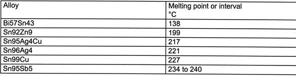
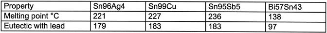
The liquidus temperature (the temperature above which solder becomes totally liquid) should be low enough. Otherwise, components and the PCB may be thermally damaged during the process. In general, this would mean that 260°C should not be exceeded. Most components are at best specified to this limiting temperature. On the other hand, the solidus temperature (below which the alloy becomes fully solid) should be high enough to ensure reliability of the solder joint during use. This mechanical ‘solidity’ must even exist at somewhat elevated temperatures. The industry usually demands adequate performance of the joints at working temperatures of up to 125°C. The melting point of the eutectic tin-lead solder (at 183°C) provides a reasonable compromise.
Metallurgy
A basic requirement that any alternative solder alloy has to fulfill is its ability to wet a wide variety of possible metallizations on the board as well as on the leads of components (gold, silver, copper, palladium, tin, nickel, iron). Ideally, one would wish that the continued use of the present fluxing systems would be possible. Aggressive fluxes are rejected by the industry because of their potential corrosive properties and possible electro-migration. Neither should any of the alloys tend to oxidize easily, as that would be detrimental to the solder wave. Oxide formation on the solder surface may also lead, in the long term, to corrosion. Furthermore, the solder joints should meet the demands for reliability and defect rates set by the industry.
Environment and health
The alloys and their constituents used should not be toxic or hazardous in any way. Therefore, alloys containing lead, cadmium, mercury and thallium, which would be excellent from a technical point of view, cannot be used due to their human and environmental toxicity. Relatively easy recycling is another prerogative that modern industrial society cannot do without.
Economy and availability
Because of the importance of the electronic joining process, any metal or element in solders must be available in the right quantity and at realistic price.
Choice of alloy constituents
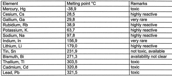
The main contributor to any alloy has to be a metal with a low melting point. Lead, cadmium, thallium and mercury have to be excluded as mentioned earlier. Gallium and indium are simply not available at the required quantities to serve as a basis to new alloys. The alkaline metals are too reactive and even small quantities leadto strong oxide formation. These oxidesmay show as dross or in the form of cor-rosive reagents. Bismuth production depends on lead mining (as does silver, etc.). Presently, we do not anticipate a shortage; however, if the production of lead should be curtailed, the potential of bismuth supplies diminishing is a possibility.
It seems that only tin may be used as a base for any new alloy (table 1). As it exhibits a high melting point of 232°C, alloying additives will become necessary to reduce the liquidus temperature (ideally to 183°C, as with tin-lead).
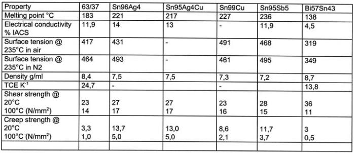
To judge the usefulness for the soldering process, the physical properties have to be investigated. These, naturally, have to include such aspects as wetting, resistance to corrosion, and thermo mechanical stability. It becomes apparent (table 3) that the mechanical properties of alternative solders are quite different from those of tin-lead. The increased strength may be an advantage; however it could also backfire with such problems as tombstoning.
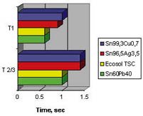
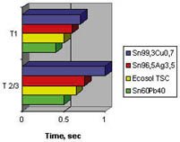
Wetting may be investigated with a wetting balance. We learn that wetting depends very definitely on the different environmental conditions. Furthermore, there is a strong dependence on the type of substrate material. Wetting on copper is insufficient for tin-zinc and tin-antimony alloys. At 250°C it is tin-silver that delivers the best wetting behavior for lead-free alloys. Bi57Sn43 wets extremely well at soldering temperatures of about 250°C (112°C above its liquidus). The best results are usually obtained with tinned nickel substrates. The ternary alloy Sn95Ag4Cu behaves very similar to Sn96Ag4.
In general, it must be stated that lead-free solders wet not as well as those of tin-lead. The use of an inert atmosphere recommends itself, and this disadvantaged can perhaps be compensated with it.
Contaminantsin the solder
Contaminants in the solder can have dire consequences. In the case of lead-free solders, a contamination with lead lowers the solidus temperature of the alloy. If the contamination increases beyond a certain level, ternary phases appear in the joint. The melting point of these ternary phases lies far below the melting point of the original alloy. The result is a drastic reduction of the reliability of the joint. There are cases where the joint showed cracks even during cooling.
Hand soldering
In this case the substitution of the tin-lead solders seems to be relatively simple. The eutectic tin-copper alloy may offer itself as a substitute. This alloy lends itself for repair and can even be used to touch up joints made with traditional tin-lead solders. Obviously, the process temperatures are higher. However, from a technical point of view, no major changes have to be instituted for the process. The higher soldering temperature may mean that the time used to solder an individual joint may have to be increased slightly. This could be a problem in high volume production environments. Bi-bearing solder wire is not available. Such wires cannot be made with the methods presently employed.
Wave or flow soldering
Wave soldering with lead-free alloys will pose more significant problems. The alloys most likely to be preferred are based on the tin-silver system. It is absolutely adamant that the total absence of lead is required. Particularly in larger solder joints or in through-hole joints, contamination with lead can cause major predicaments. It is again the life expectancy of the joint that is inhibited. It is very likely that lead-reach phases establish themselves within the joint during cooling. Their melting point lies well below the rest of the alloy. Removing a lead contamination from the solder bath can only be achieved by a total exchange of the solder. The cost associated with such measures is considerable.
Tin-copper or tin-silver alloys can be considered as alternatives. In the case of tin-silver alloys, one would not necessarily be limited to the eutectic alloy. The high price of silver may be a limiting factor. Soldering should still work well with a content limited to 2% of silver. When soldering with tin-silver, one has to expect enrichment with copper during longer use. Copper in the tin-silver alloy will change the properties of the original solder. The wetting properties of tin-silver are good. However, there are still open questions with regard to tin-copper, as wetting of tin-copper does not really measure up to requirements.
The soldering process should be carried out in nitrogen-capable equipment. Inerting the process greatly reduces the creation of dross. It also inhibits the ‘burning’ or depletion of the flux activators prior to reaching the wave. Soldering temperatures must be high enough to achieve a practically defect free result. Tests have shown that soldering temperatures up to 280°C may become necessary. This will put additional thermal stress on board and components. It may, however, be possible to optimize the process so that only 260°C is required in the solder bath. This value would represent a temperature that is only 10K higher than the traditional temperature of wave soldering units.
With regard to fluxes, during wave soldering, attention must be paid to the higher pre-heat temperatures. These are required to limit the temperature ‘jump’ (Delta T) between pre-heat and entrance into the wave to an acceptable value. Higher pre-heat and higher soldering temperatures impact directly on the flux constituents. Their thermal stability has to be higher than those commonly found in modern low solids fluxes. At higher temperatures, the evaporation rate of carboxylic acids is higher despite the fact that the boiling temperature has not been reached. Fluxes with higher solids content and a certain amount of rosin are more advantageous in these cases. Because of the higher temperatures, one may consider switching to VOC-free fluxes that are water based. Their use may be facilitated due to other process parameters.
Reflow soldering
High temperatures during the reflow process play a much more central role than in wave soldering. The dwell time for the PCB in the peak zone is a great deal longer than the immersion time during the wave soldering procedure. We find again that an inert atmosphere will allow us to lower the peak temperature by a few degrees. Besides the two (by now well-known) alternatives of tin-silver and tin-copper, the tin-silver-copper eutectic (melting point 217°C) offers a third possible choice with lower thrall requirements. This alloy exhibits noticeably better wetting characteristics at 235°C than we encounter, e.g. using the binary SnAg or SnCu solders. Reflow in vapor phase (referred to as condensation soldering) could in future gain new popularity when soldering with lead-free products.
Lead-free paste differs little from those made with lead-bearing alloys. They look quite similar, although they may appear to be somewhat lighter in color. The metal powder exhibits neither a different corn shape nor a different size distribution. In order that we achieve similar printing performance, we have to aim at a similar relationship between the different volumes: Flux against metal about the same as in the ‘old’ pastes. As the densities of the SnAg alloys are lower than those of SnPb systems, we have to adjust to a lower metal content (always stated in mass percentage). Since this would entail higher flux content, one would expect more flux residues. However, this is not so. Additional cost for the lead-free alloy have a smaller impact for pastes than for bar solder: the production cost for powder and paste must be taken into consideration. Two percent silver can be found already in most of the common lead-bearing pastes anyway. The same flux activator systems used for pastes of the RMA type can still be used. However, care must be taken during introduction that the solder joint remains free of voids. Here we have a little dilemma, as such occurrences cannot be noticed when looking at the outside of the joint. X-ray methods (tomography or laminography) will prove their value during the early stages of introduction.
Soldering with pastes that contain low melting alloys is entirely possible. Powder of bismuth containing alloys can be produced, and thus pastes can be mixed. Solder pastes consisting of the Bi57Sn43 alloy need much lower process temperatures. Since those chemical reactions that are responsible for the removal of existing oxide films perform much slower, wetting would be a concern. Special attention will have to be given to the establishment of proper thermal reflow profiles. These have to be derived using information on the wettability of the PCB (the surface) as well as those of all the components. Furthermore, a strict lead-free situation must be aimed at. The presence of lead would, otherwise, direct to phases within the solder joint that have solidus temperatures of 96°C only.
An outlook
There are products available for the lead-free soldering process. However, the user will have to do a lot of work prior to introducing lead-free products. Before the legislation comes into force, we will have to ensure that the chosen process will yield reliable products. Promising solutions are in sight. Yet, there are many more problems that need solving. We only have started to prepare ourselves for a switch to lead-free soldering processes. Some lead-free products are in fabrication. These, however, are directed at special solutions only. They were not initiated with the intent to safeguard our environment. In our judgment, the best solution at present seems to be offered by the ternary eutectic alloy SnAgCu.
Many questions remain unanswered. They have to be solved by research efforts. The manufacturers of pastes and solders alone cannot do this. Every partner has to be taken to task: users, equipment manufacturers, PCB shops and research centers. It is most important for the different economies to resolve these questions:
PCBs for the lead-free process?
Components for the lead-free process?
Which alloys can be provided in which form?
Which soldering processes will meet the requirements of alternative alloys?
What must we do about repair?
Can we continue to use the present fluxes?
What about the cost impact?
Can we achieve the same yield with regard to defect rates?
There is no replacement for the high-melting lead-bearing solders
There are potential advantages when using lead-free alloys: for example, to meet the requirements of the automotive industry for higher application temperatures. However, we need intensive efforts in research and development to meet all the looming deadlines. We may have to experiment with novel alloy systems if we have to lower the process temperatures for wave and reflow soldering.
zusammenfassung
Die Diskussion um die EU-Gesetzgebung zur Verbannung von Blei aus Elektronikprodukten schlägt hohe Wellen. Wobei derzeit immer noch Lücken bestehen, beispielsweise wie ist “bleifrei” definiert bei mobilen Geräten mit Bleiakku zur Spannungsversorgung bzw. bei Fahrzeugen mit voluminösen Batterien? Dabei wird die Zeit allmählich knapp, insbesondere für Großunternehmen, in denen die Umstellungsprozedur lange Wege zurücklegen muß. Nachdem vom globalen Blei-Jahresverbrauch lediglich 0,5 % auf die Elektronik entfallen, stellt sich natürlich die Frage, was passiert eigentlich mit den restlichen 99,5 % ? Ironisch formuliert: Wirken sich diese nicht auch toxisch aus?
Résumé La discussion autour de la législation européenne visant à bannir le plomb des produits électroniques fait des vagues. Des lacunes continuent de persister par exemple sur la façon de définir l’absence de plomb dans le cas des appareils mobiles alimentés par des accumulateurs au plomb ou des véhicules équipés de grosses batteries au plomb. Or le temps presse, notamment pour les grandes entreprises dans lesquelles le processus de conversion est complexe. Dans la mesure où 0,5% seulement de la consommation totale de plomb est imputable à l’électronique, on est bien sûr en droit de se demander ce qu’il en est des 99,5% restants? Ou plus ironiquement, ne sont-ils pas toxiques, eux? Sommario
La discussione riguardo alla legislazione europea per l’eliminazione del piombo dai prodotti elettronici fa molto parlare. Infatti vi sono ancora molti concetti poco chiari come per esempio la definizione di „senza piombo“ nel caso di apparecchi mobili con accumulatori di piombo per l’alimentazione di tensione oppure in caso di veicoli con grandi batterie al piombo. I tempi diventano sempre più stretti soprattutto per le grandi aziende in cui il processo di trasformazione richiede molto tempo. Se si tiene conto che il consumo annuale mondiale di piombo ricade solo per lo 0,5 % sui componenti elettronici, ci si chiede naturalmente cosa succeda con il rimanente 99,5 %. Per formularlo in maniera ironica: non è nocivo anche il resto?
Fax +49-9342-889-200
EPP 153
Unsere Webinar-Empfehlung
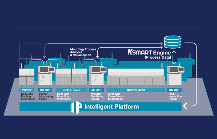
Die Nutzung der 3D-Mess- und Prozessdaten bringt die Produktionssteuerung auf die nächste Stufe. Echte 3D-Messung ermöglicht KI-basierte Prozessmodellierung zur Vorhersage von Parameteränderungen und -defekten oder zur Ursachenanalyse bis hin zu einzelnen Werkzeugen und Best…
Teilen:


