With the prevailing trend in miniaturization of consumer products, QFPs are giving way to BGAs, and these are reducing in size to become microbars. The continuing drive towards further miniaturization and increased functionality is hastening the move towards CSPs and flip-chips.
Keith Merrington, Assembleon
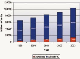
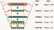
Expectations drive the market towards increasingly portable and wearable electronic products (figure 1). Advanced packages are forecast to constitute a larger slice of the total integrated circuit population. Figure 2 illustrates the progression from leaded ICs to bare silicon die, bringing with it an approximately 10-fold reduction in component area (figure 2). Because the market is preparing to use these ultra-fine pitch components in high volume, there is a corresponding need for advanced placement capability. Furthermore, cost pressure dictates that the placement machines not only handle a variety of fine-pitch components, but also do so at lowest cost per placement (cop). This requirement brings many additional considerations into the equation, such as uptime efficiency.
Issues for placing ultra-fine pitch parts
Board assemblers are facing challenges presented by trends in substrates, components and processes. Higher placement accuracy is required to deal with finer line resolution, the increasing use of miniature components such as flip-chip, 0201 and 0101, and the coming trend from solder paste to conductive glue. Smaller, or even no fiducials, and increased I/O count demand higher-resolution vision systems. Thin, fragile components necessitate controlled, low-force placement. Versatility is required to deal with the increasing use of flex and ceramic substrates, wafers and fluxing.
In fact, few component mounters on the market can consistently and reliably assemble ultra-fine pitch components, with even fewer operating at a rate which allows integration with high-speed chipshooters on the production line. The optimum combination of accuracy and speed implies a need for very high machine stability, with vision alignment and placement systems operating in parallel to minimize cycle time. Direct pick from a variety of die feeding options will also add to the speed and flexibility of the machine. Flexibility to handle a wide range of substrate types and sizes, and components from 0101s through advanced packages to odd-forms, will help to ensure maximum machine utilization and return on investment.
Placement accuracy
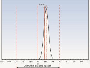
Flip-chips demand ultimate placement accuracy to achieve the highest quality products. The common demand for flip-chip process capability is a Cpk value of 1.67 (figure 3), effectively meaning one placement error per million placements (1ppm). The increased need for higher quality and smaller process windows will require tighter accuracies with a Cpk of 2.0. Because defect-free placement is required not just in short bursts but over an extended period, long-term stability is the key requirement for flip-chip processing.
Keeping the machine within narrow process limits over time requires a highly rigid structure and smooth, precise robotic positioning. Users are looking to advanced robotic technology such as low-friction linear motor drive, progressive acceleration and deceleration allowing accuracy adjustments according to device size and pitch, and Z-axis programmability to control placement, coupled with force control, to prevent damage to parts. The weight of feeders and feeder trolleys, which can be considerable, should be decoupled from the machine frame to avoid jeopardizing the stability of the frame.
Self-calibrating vision system
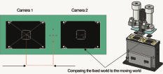
For placement of 75mm bump flip-chips with 120mm pitch an advanced, self-calibrating vision alignment system is required. Such a system (figure 4) can use both local and global fiducial alignment to correct for artwork offset, and a component alignment system also incorporating CCD cameras and multiple light sources, to determine the exact orientation with respect to a reference plate. Any deviation can be corrected using information from both fiducial and component alignment systems. With all cameras simultaneously reading a reference pattern at PCB level, minor geometric shifts due, for example, to temperature changes, can be detected and compensated for.
Direct pick of parts from trays, without the need for a shuttle robot, also helps to reduce cycle time and will remove the possibility of contaminating the bumps by the shuttle device. With multiple precision placement heads, a rate of 4500 components per hour (cph) can be achieved, with the result that the fine-pitch placement machine can be aligned with high-speed chipshooters with no PCB cycle time penalty.
Flexible lighting
The greatest flexibility to span the IC range from QFP to flip-chip is provided by a vision system that allows components to be lit from the front, the back or from the side. Leaded QFPs are best lit from behind because no spurious reflections will show. BGAs, on the other hand, require side or shear lighting to illuminate the entire bump pattern on the bottom of the package. Being able to combine front lighting with side lighting, with each having independently adjustable intensities, gives a truly flexible system capable of recognizing the most diverse of packages.
One of the problems with small packages is the limited pad size, which results in very small quantities of solder paste. Additional fluxing may be required and becomes part of the assembly cycle. This may be achieved by including a fluxer in-line with the pick&place machine, but is more cost-effectively implemented with an integral dip fluxer, with flexibility for configuration either before or after component alignment, as required by the user, and adjustability of flux height.
The cost of packaging components in tape can be considerable, so it makes sense to perform as many operations as possible at wafer level, and future-proofing of the pick&place solution demands the flexibility for direct feed from wafer. An output from wafers of up to 2400 die/hour can be achieved with a handler that automatical-ly expands the wafer, picks a good die,and flips them if required. Combinedwith options for direct die feeding fromwaffle trays, surftape and gel-pak, direct wafer feeding provides optimum flexibility for handling tomorrow’s components today.
Modularity the key
Traditionally, a medium-to-high-volume SMT production line has included two placement machines – a turret-style chipshooter for small components and a flexible odd-part and fine pitch placement machine. This machine pairing has been fairly logical for many typical assemblies, with between 60 and 90% chips, because the ratio of chips to large and fine pitch parts has roughly corresponded to the speed difference in the two machines.
However, with the increasing use of advanced packaging, the ratio is changing, so balancing machine output to maximize throughput becomes very difficult. While fast for placing chips, turret machines are large and expensive. They also vibrate, negatively influencing the placement accuracy. Because of increasing packaging diversity it is important that any machine purchased today should be able to handle all package types and packaging for maximum flexibility. However, when turret machines are operating relatively slowly for placing larger components, cpp rises. Finally, an added complexity with the dual-machine configuration is that the operating software and feeders are often different for the two machines, even when they come from the same vendor.
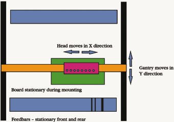
In the last decade, there have been significant strides in XY gantry system design (figure 5). The modular gantry-type pick& place machine operates on a parallel-placement concept, with multiple heads placing components simultaneously as the board moves through the machine. This concept provides high accuracy, with the versatility to place chips, large parts and even odd-forms through fast, auto exchange of nozzles and grippers. Two can be put in line with closely balanced cycle time to achieve speeds equal to a turret machine. They are also smaller and less costly than turret machines.
An additional benefit of gantry systems with stationary feeder bars, in contrast with turret systems, is that feederbar exchange systems can be used to minimize changeover times. In a high-mix environment, there is considerable competitive advantage in changing over an entire placement line in a matter of minutes. Also, because it is of very low mechanical complexity, and designed on a replace-not-fix repair concept, the gantry machinedelivers high uptime efficiency, helping users to gain competitive advantage from lowest cpp.
Future-proofing the factory floor
Electronics manufacturers are looking to pick&place machinery providers to give them a smooth upgrade path that will enable them to deal with packaging technologies as they come along, while limiting capital costs. Operating flexibility is also required to deal with increasing product diversity and shorter time-to-market, necessitating faster changeovers and easier flowline reconfiguration. The modular approach to pick&place machine design has clear advantages in both respects, its flexibility derived from the freedom to bolt on up-to-the-minute placement capability which, given feeder and software compatibility, is quickly integrated into the flowline.
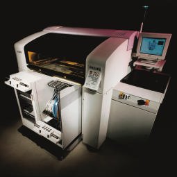
In the design of its ACM Micro (figure 6) placement machine, Assembléon has adopted high-speed gantry technology for optimum flexibility and cpp, with advanced self-calibrating vision alignment for handling BGA, CSP and flip-chip, as well as the capability to cope with all current packaging types. The machines are modular in design and offer hardware and software interoperability, combining versatility for today with upgradeability for tomorrow’s production requirements.
EPP 166
Zusammenfassung
Die weitergehende Minaturisierung der Elektronikgeräte führt zwangsläufig auch zu weiter verkleinerten Bauelemente, um die Baugruppen zu reduzieren. In der Bestückung heißt das, daß der automatisierten Verarbeitung von ´sehr kleinen Bauformen aller Art wie 0201, 0101, BGA, MicroBGA, CSP oder anderen Advanced-Packages hohe Bedeutung zukommt. Die Placer dafür müssen hohe Anforderungen erfüllen.
Résumé
La miniaturisation incessante des appareils électroniques entraîne nécessairement une réduction de la taille des composants en vue de diminuer celle des circuits. Au niveau de l’équipement, cela signifie que la mise en œuvre automatisée de composants de très faibles dimensions comme 0201, 0101, BGA, MicroBGA, CSP ou d’autres joue un rôle très important. Les équipements d’implantation doivent par conséquent faire face à des exigences élevées.
Sommario
La sempre maggiore miniaturizzazione degli apparecchi elettronici implica naturalmente anche una continua miniaturizzazione dei loro componenti, al fine di poter ridurre anche le dimensioni dei gruppi costruttivi. Per quanto riguarda i sistemi di applicazione ciò significa che il trattamento e la manipolazione di forme piccolissime di qualsiasi tipo come 0201, 0101, BGA, MicroBGA, CSP o altri Advanced-Packages diventeranno sempre più importanti. I relativi Placer dovranno dunque soddisfare severi requisiti.
Unsere Webinar-Empfehlung
.png)
Conformal Coating ist ein wichtiges Verfahren, um elektronische Baugruppen vor dem vorzeitigen Ausfall zu schützen. Damit bekommt der Beschichtungsprozess eine immer höhere Bedeutung. Dabei ist die Auftragsstärke ein wichtiges Qualitätskriterium. Nur eine zeitnahe schnelle Messung…
Teilen:


