Advanced-packaging dispensing in PCB assembly primarily concerns underfilling an increasing range of modern components. Although it also encompasses the encapsulation of wire-bonded chip-on-board (COB) devices, and more recently µBGAs, these are at present more limited electronics production applications.
Although underfilling has traditionally been a part of the flip-chip assembly process, many manufacturers are now opting to underfill a wide range of other components including BGAs, µBGAs and CSPs. This is because underfilling is an effective way to help ensure the long-term reliability of such devices, by supporting and protecting their component-to-board interconnects from damage in the field.
Although this includes damage caused by physical vibrations and flexing of the PCB itself, the primary role of the underfill is to protect against stress induced by differences in the coefficient of thermal expansion (CTE) between the silicon die of the device and the PCB substrate during routine operational thermal cycling. Without underfill, this stress would be absorbed entirely by the solder bumps used to connect these types of component to the PCB. And as the net area of these bumps is far less than the combined areas of the die and substrate, the resultant forces can be very large.
The underfilling process is, therefore, becoming extremely popular for use in the manufacture of portable or high-reliability electronics products that have to be durable or are intended for use in harsh operating environments. This encompasses an increasingly wide range of professional and even consumer products.
„A prime example is mobile phones,“ says Jamie Maughan, principal applications engineer at Speedline Camalot. „Due to their high functionality and miniaturised size, these products demand the use of modern component packages yet have to withstand rigours typical of harsh operating environments. These include being physically dropped, or exposed to huge temperature changes ranging from being left in a car overnight in freezing conditions to sitting in direct sunlight.“
Underfill can also be justified for individual devices on any board that could be particularly prone to future reliability problems identified during accelerated product life tests. The interconnects of components in central areas of a board more prone to flexing, for example, can be protected in this way. Underfilling is, therefore, fast becoming a routine assembly function, and the following ten-point guide is designed to help users which are about to install an underfill process.
1. In-line or stand-alone process
One of the first considerations is whether you need an in-line or stand-alone underfill process. In an in-line process the underfill dispenser will be positioned after the (typically in-circuit) test stage. Whereas in a stand-alone process, which means either a stand-alone machine or separate automated underfill line, it will be positioned separately. The latter can suit production environments where a number of lines are used to produce PCBs that don’t always require underfill and the manufacturer wishes to avoid the expense of having to invest in four separate underfill dispensers. But for medium to high volume production, in-line will usually be required.
2. Heating method:contact or non-contact
During the underfill process, a fillet of fluid is dispensed around the sides of a device and allowed to flow beneath it via capillary action to fill the space between the die, substrate and interconnect bumps. „Relying on capillary action alone, however, is not time efficient,“ continues Maughan. „Therefore to promote a faster uniform flow of the underfill material, the PCB substrate (or MCM for certain applications) should be heated to around 60 to 65¡C during a three stage pre, dispense, and post-heating process. This heat can be supplied by either a contact or non-contact method which will determine the type of dispensing machine platform that is required.“
In contact heating, a hot plate (of around 70°C) is used to heat the PCB by making contact with the underside of the substrate at a specified point beneath the device to be underfilled. This is a quick and precise method that benefits from exploiting a vacuum clamp system to hold the board flat during heating and deposition. The drawback is that it requires an underside heating area that is free of components which can make it problematic on double-sided boards.
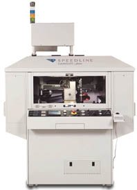
In non-coating heating, thermal energy is supplied to an entire board via forced hot-air convection which is sometimes supplemented by IR heating. Although this tends to be a more cost-effective method than contact heating, it also tends to be slower as the entire board needs to be heated from ambient temperature in a similar fashion to a reflow oven. Speedline Camalot, for example, offers both types of machines across a broad range of dispensers ranging from its stand-alone (contact) 1818 through the 3700 (contact) and 3600 (non-contact) models up to its flagship Xyflex (contact), with additional non-contact version due next year. The 3600 exploits an integrated oven for consistent non-contact heating of FR4, ceramic and flexible substrates, as well as MCM assemblies. Dual forced hot air convection and quartz heating is also used to maintain components at stable tempera-ture profiles over the entire heating process.
3. Choosing an equipment platform
The next step is to select a suitable dispensing machine platform. This needs to be capable of dispensing precise and consistent volumes of underfill material at the required throughput to meet the inherently tight process tolerances of any underfill process.
„This is why all our dispensers exploit the same high quality, patented, rotary positive displacement dispense pump technology,“ underlines Maughan. „This is a highly accurate and efficient method of dispensing underfill without loss of throughput, that helps keep production costs low. Both the 3600 and 3700 are in-line dispensers that can supply flip-chip underfill to 25-micron precision and 50-micron repeatability at a typical throughput of around 300 underfills per hour (uph). When dispensing flip-chip underfill, their dispense needles are positioned 3 to -5-mils (75 to 25-microns) away from the edge of the device (needle gap) and 1 to3-mils (25 to 75-microns) off the substrate using a Z-axis compensator to guarantee precision.“
At the top end of the scale is the industry-leading Xyflex four-head dispense system that can achieve throughput rates of up to 1000uph to the same 25-micron precision and 50-micron repeatability of the 3600 and 3700 models. In terms of cost, underfill dispense platforms can range from an entry-level circa US$80K up to approximately US$400K.
4. Ensuring applicationof right underfill volume
Another major consideration when applying underfill is the volume of material dispensed. If too little underfill is applied, the risk of voids increases dramatically and its protective abilities diminish. (Voids are bubbles of trapped air left within the underfill which can trap moisture and, during thermal cycling, expand (popcorn effect) to cause major damage to the PCB substrate and component itself.) „The primary aim is, of course, to completely and evenly fill the gaps underneath the device to prevent voids,“ declares Maughan. „If too much underfill is applied, the dimensions of the package effectively increase with the greater risk of cracks or delaminations within the die. There is also a likelihood of partially underfilling neighbouring components, while the board will also look very poor cosmetically.“
The volume required is a function of the height between the underside of the device and the substrate, and the number and size of the interconnect balls. It can be calculated by subtracting from the volume of the entire space between the die and substrate, the volume of the interconnect bumps. If a small fillet of underfill is required around the edge of the device, this should be added to the required dispense volume, although this is usually applied in a separate final dispense pass. The primary role of a fillet is to visually show that the underfill of the device is successfully anchored and sealed on the board.
5. Setting needle height
In conjunction with calculating the required volume of underfill material, the corresponding dispense needle height above the PCB substrate should also be determined. This should be above the underside of the device, but below the top of it. The margin for error, therefore, depends upon the package thickness but there will typically be around 2 or 3-mil of tolerance.
Once the needle height has been established, this can be verified on the dispenser using either a laser or mechanical touch probe. Although the former is very quick, it is a more expensive alternative to the latter one.
6. Ensuring chip is aligned correctly
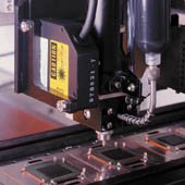
„Manufacturers must also guard against the danger of having a misaligned package which has passed electrical test, dramatically, altering the alignment and distance between the dispense needle and device,“ states Maughan. „Our machines are using a Cognex pattern-recognition system to visually inspect the exact position and orientation of each die prior to underfilling. In the case of misalignement, this automatically compensates for the travel of the dispense needle to ensure the correct offset is applied.“
7. Selecting needle diameter
The outer diameter of the dispense needle affects the needle gap and determines how much underfill material (in µlitres) can be dispensed beneath a device in a given time. Although larger needles are faster, when they finish dispensing they will leave a larger witness mark on the fillet at the edge of the device. This can be a problem on dense boards with closely spaced components.
8. Deciding on a single or L-pass
If there is a large number of balls beneath a device, extra time will be needed to allow the underfill material to flow around them, and this may require the underfill material to be applied in several stages or passes. „Typically this involves applying the underfill to either one or two adjacent sides of a device in an L-pass,“ comments Maughan. „There must, however, be a continuous flow of material with the deposit of each successive pass applied before the capillary action of the preceding one has allowed the underfill material to flow away under the device completely. The shape of the device and the maximum flow distance of the fluid beneath its die (given by its wettability and flow speed) will determine the optimum dispense pattern.“
9. Selecting underfill materials
The speed and quality of the dispense process is affected by both the performance of the dispensing machine and the underfill material. The primary function of the underfill material is twofold. First, it helps reducing temperature variants throughout the length of the device being underfilled. And second, it serves as a mechanical bond to help prevent interconnect joints cracking under the strain of PCB vibrations or flexing.
„The best way to select the most suitable material and to determine every other underfill process parameter listed above, is to perform some trials and cross-check the performance by physically removing and inspecting the device,“ summarizes Maughan. „The trick to preventing voids is to select the right material, get it to the right temperature (and therefore viscosity) to dispense, and maintain a continuous flow as the dispense needle is passed around the perimeter of the device.“
10. Selecting a furnace for curing
After being dispensed, the underfill material then needs to be subjected to an accelerated cure in a furnace. A good-quality, entrance-level convection reflow oven such as Speedline Electrovert’s Bravo is ideal as all that is typically required is a 15-min cure at around 130°C. Obviosly, a final step that cannot be overlooked, is to find a vendor who has both the prerequisite expertise and desire to partner closely with to successfully establish the best underfill assembly process in every case.
Fax: +44 (0)118 930 1401
EPP 208
Zusammenfassung
Viel wird regelmäßig zum Thema Dispensing von Underfiller verlautet, speziell, wenn es um neue Systeme geht. Doch was ist mit den technischen Grundlagen, die jeder Prozeßspezialist benötigt, um in der Fertigung kontinuierlich anständige Ergebnisse zu erzielen ? In zehn Schritten zeigen wir klar, worauf es im wesentlichen dabei ankommt.
Résumé
Beaucoup de choses sont dites sur la dispensation d’underfiller, notamment lorsqu’il s’agit de nouveaux systèmes. Mais qu’en est-il des principes techniques dont tout spécialiste de processus a besoin pour obtenir des résultats constamment bons dans la fabrication? Nous expliquons clairement l’essentiel en dix étapes.
Sommario
Soprattutto quando si discute di nuovi sistemi il Dispensing di Underfiller ricopre un ruolo di rilievo. Non bisogna però trascurare le fondamentali norme tecniche che servono ad ogni specialista di processo se desidera ottenere costantemente dei risultati soddisfacenti. Ecco dieci regole fondamentali da rispettare.
Unsere Webinar-Empfehlung
Die Nutzung der 3D-Mess- und Prozessdaten bringt die Produktionssteuerung auf die nächste Stufe. Echte 3D-Messung ermöglicht KI-basierte Prozessmodellierung zur Vorhersage von Parameteränderungen und -defekten oder zur Ursachenanalyse bis hin zu einzelnen Werkzeugen und Best…
Teilen:


