Vectorless board test cannot replace pattern-driven verification of build-in components and its functional interactions, and the boundary scan technology. Vectorless does provide a reliable alternative where these techniques are either unnecessary or not viable for reasons of cost, complexity or timescale.
Andrew Smithers, SPEA U.K., Wareham, Dorset
The test department is facing many problems because circuits are now highly integrated and miniaturized. IC technology has expanded: pin count has gone up, device size has gone down. At the same time, test access has steadily decreased with the pressure on board design to cram greater component densities onto even smaller boards.
As device complexity increases, the problems in generating and verifying appropriate vectors for these devices become correspondingly harder. Clock speeds are very high, and communication protocols are exceeding the capabilities of test equipment and staff alike. In addition, the time-to-market pressures are reducing the acceptable lead times for programming and fixture construction. Finally, the data on functionality may simply be unavailable due to remote generation of the data or commercial sensitivity; this problem is even more pronounced in subcontracting.
A solution
Flying-probe testers are, in many ways, the answer to the users‘ dreams. Test pads are no longer absolutely necessary, and even very fine-pitch components can now be directly probed. Probing of advanced packages such as BGA and QFP is, in many cases, simply not possible on a conventional bed-of-nails fixture – the flying-prober provides the only viable solution to this. The arrival of second-generation flying probers with very fast mechanical systems based on linear motors and air bearings has done much to eliminate the trade-off between accuracy and speed that was an issue of first-generation probers.
Vectorless test techniques rely on the principle that a faulty device is statistically very improbable. It is far more likely that an IC is either misplaced or incorrectly soldered. This is even more probable with the increasing use of BGA, PGA and QFP packages.
The techniques
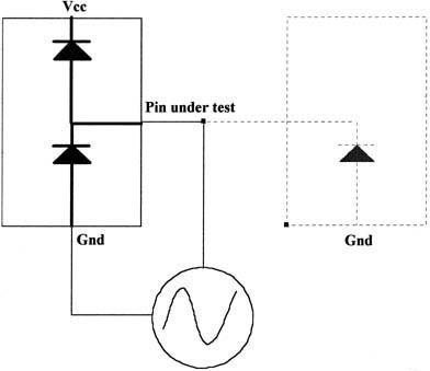
For SPEA testers there are three complementary techniques called JunctionScan, CurrentScan and ElectroScan. JunctionScan is the simplest technique to understand. It relies on the presence of protection diodes between pins of the device and Ground/VCC. The protection diodes are verified by applying a small current source and measuring the corresponding forward voltage. If this is around 0.7V, the protection diode exists, and so the IC is correctly placed and soldered. The limit with JuctionScan occurs when an IC is to be bussed with other ones. For example, a test of the diode path will result in a reading of 0.7V even if the IC is missing, due to a parallel current path through a bussed IC. To test bussed ICs, a more complicated approach is required.
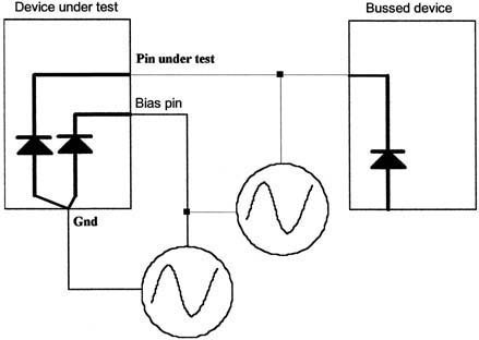
CurrentScan is an extension of the basic Junction Scan technique. Here, the protection diodes are still tested, but this time its current is actively controlled by a selected bias pin of the device. This means that measured current applies to the DUT (device under test) and not to any other components connected on the bus.
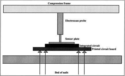
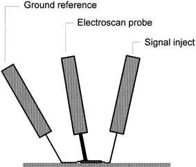
ElectroScan is the entirely different approach to open-pin testing. This technique does not rely on the tests of protection diodes but instead detects the electromagnetic field produced by small currents injected through each pin in turn to ground.
All the vectorless techniques are directly applicable to test fixtures. JunctionScan and CurrentScan are implemented using special software algorithms, while ElectroScan requires additional hardware built into the test fixture. ElectroScan probes may be integrated into frames for pneumatic fixtures or top-hat arrangements for vacuum fixtures. Additionally, the sensors may be incorporated into the base of the fixture for bottom side mounted devices. Of course, using these methods on a bed-of-nail system does nothing to relieve the problems of component density and lack of test pads.
Flying prober
The vectorless techniques are applicable to flying probers. Since JunctionScan and CurrentScan are software implementa-tions, they are easily shifted on a flying prober. However, the transfer of the ElectroScan technology onto a flying prober has not been so simple. Such a prober must be unaffected by the magnetic fields generated by motors and drive units of the tester, and must also withstand the acceleration of the flying heads.
There are two situations in which ElectroScan may be applied on a flying probe: The PCB is mounted with the devices facing upwards where probing is performed on pins; the PCB is inverted to allow probing on the bottom-side. In this case, ElectroScan must be performed from underneath using fixed probes.
For top-side Electroscan probing, sophisticated hardware and software is required to manage the dual functions of applying signals via the probes and also accurately placing the sensor. The software must be capable of on-the-fly probe selection for debug purposes and also, ideally, to perform a learning function for placement of the sensor probe. Since the probe sensor plate must be far smaller than the surface area of an IC, due to space limitations, it is vital that the sensor be positioned so as to obtain the maximum signal strength from the detected signal. The optimum position for a sensor is dependant on the outlay of the IC and so must be learned during debugging. This learning process would be time-consuming and error-prone if attempted manually.
It is also vital that the Electroscan hardware retracts unobtrusively so as not to interfere with the normal functioning of the flying prober. The ElectroScan objects may be placed in a fixture for high-volume production or alternatively magnetically attached to the base plate of loading shuttle.
In this combination, the vectorless techniques provide a powerful tool. Simple diode junction testing is adequate for dealing with single ICs on an otherwise predominately discrete board. The more discriminating techniques of CurrentScan and ElectroScan are necessary for bussed digital devices. The real value of all these methods is that no knowledge of the functionality of the ICs is required. This has important advantages for almost every user, and especially for subcontractors.
On a flying prober where all three techniques can be programmed and debugged within minutes, the time and cost saving over conventional techniques can be enormous. A high confidence-level test can be performed on a prototype typically on the same day that this board is available from R&D. Considering that such boards are frequently hand-built with the resultant increased likelihood of assembly errors, this represents a tremendous advantage in terms of lead time and design-to-market.
Side-effects
Another valuable side-effect of vectorless test technique is that, if the design or functionality of an IC changes during the product development or life cycle, little changes would be necessary to the test program. This can be put in contrast with the results of a mid-lifecycle change to an EPLD or gate array tested using vectors. When production starts in volume, the test process is immediately available and can, of course, be readily transferred to a regular bed-of-nails tester at a later stage when necessary.
There are a few other areas in which the Electroscan technique can prove advantageous. Since it measures the electromagnetic field caused by a current flow, it can be used to verify the presence of other components. Connectors may be tested by placing the Electroscan head so as to detect the current injected. If the connector is not present – the test fails. Electrolytics may also be tested for orientation. Such arrangements are notoriously difficult to detect using conventional techniques.
Zusammenfassung
Mit vektorlosen Testmethoden kann man in der Fertigungsprüfung von Baugruppen rasch die produktionstypischen Defekt wie Unterbrechungen, Schlüsse oder verdrehte Bauteile erkennen. Kombiniert mit einer leistungsfähigen Flying-Probe, die diese sowie andere Prüfmethoden ausführt, ist bei kleinen Serien, Prototypen und Nullserien sogar der Testadapter unnötig.
Résumé
Les méthodes de test non vectorielles permettent de détecter rapidement, dans le contrôle de fabrication des modules, les défauts typiques que sont les interruptions, les faux contacts ou les composants mal placés. En associant ces méthodes à un Flying-Probe efficace, qui exécute cette méthode ainsi que d’autres, il devient même possible d’éliminer l’adaptateur de test pour les petites séries, les prototypes et les séries zéro.
Sommario
Mediante i metodi test privi di vettori, nel controllo della produzione di componenti modulari, è possibile riconoscere rapidamente e tempestivamente i tipici difetti di produzione, come per esempio interruzioni, terminali o componenti spostati dalla loro posizione. In combinazione ad un’efficiente prova Flying, la quale esegue a sua volta questi o anche altri metodi di controllo, diventa perfino superfluo l’adattatore per test nelle piccole serie, prototipi e serie d’origine.
Fax +49-6408-7305
EPP 352
Unsere Webinar-Empfehlung
Die Zuhörer erhalten Informationen zur Effizienzsteigerung von AOI-Systemen bei Nutzung von Digitalen Zwillingen von der zu prüfende Baugruppe bzw. des eingesetzten Inspektionssystems.
Teilen:


